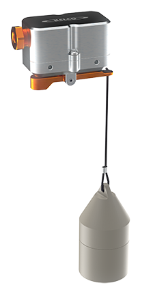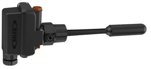
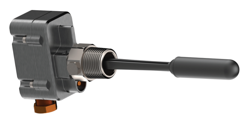
Industrial / mining-grade side-entry float level switch — same proven action as the L Series but in a billet-aluminium housing with a 316 stainless steel process connection. Polypropylene float and arm; 5–500 V AC, 15 A S.P.D.T. micro-switch (LM-H) with built-in manual override, or low-voltage gold-contact micro-switch (LM-L).
LM Series
Level Switches
Features
- 5–500 V AC, 15 A S.P.D.T. micro-switch (LM-H)
- Low-voltage gold-contact model available (LM-L)
- 316 stainless process connection
- Super-tough billet aluminium housing
- Manual override built in
- 1″ BSP and 1″ NPT models available
- Seal-less magnetic drive
- Weatherproof IP67 housing
- Easily serviceable
The LM Series is built tough for arduous service, giving a reliable, accurate solution to tank level control. 316 stainless steel process connection + CNC-machined billet aluminium electrical housing + polypropylene float and arm. The standard 5 to 500 V S.P.D.T. micro-switch (LM-H) suits general control circuits — ideal for pump starters, relay logic, contactors and timers — and the low-voltage gold contact S.P.D.T. micro-switch (LM-L) is for PLC, telemetry and low voltage control. Manual override on all LM models. The arm tip travels 45 mm each side of horizontal centre; switch operates ±2° around horizontal.
Select Model
Trade customers should contact sales@kelco.co.nz for account pricing.
Ordering — Available Models
| Model Number | Description |
|---|---|
| LM-H-25B | Standard heavy-duty switch, 1" BSP |
| LM-H-25N | Standard heavy-duty switch, 1" NPT |
| LM-L-25B | Low-voltage gold-contact model (L) — gold-contact S.P.D.T. microswitch, 1" BSP |
| LM-L-25N | Low-voltage gold-contact model (L) — gold-contact S.P.D.T. microswitch, 1" NPT |
Operating Limitations
| Maximum operating temperature (process liquid) | 80 °C / 176 °F |
|---|---|
| Minimum operating temperature | -60 °C / -76 °F |
| Maximum submergence of the float | 100 m / 328 ft |
| Float design pressure | 100 metres head pressure (980 kPa / 142 psi) |
| Minimum burst pressure (polypropylene float, ambient) | 1800 kPa / 260 psi (183 m / 602 ft of head) |
| Minimum burst pressure (switch body, ambient) | 800 bar / 11 600 psi |
| Rated pressure of the stainless body | 400 bar |
| Minimum liquid SG | 0.95 |
| Ingress protection rating | IP67 |
| Clearance above and below the switch centre line | 25 mm minimum, for free movement of the float |
Electrical Data
| Switch type | S.P.D.T. heavy-duty mechanical micro-switch |
|---|---|
| Voltage range | 5 to 500 V AC (minimum load 160 mA at 5 V DC) |
| Direct motor control | Up to ¼ HP (approx. 185 W) at 240 V AC. For larger motors use a contactor or relay. |
| Absolute limits (LM-H) | 500 V AC maximum; 15 A maximum (10 A at 500 V AC); 5 V DC and 160 mA minimum. Maximum voltage and maximum current cannot be applied together — use the ratings below for the limit at each voltage and load type. |
| LM-H current rating at 125 V AC | Non-inductive loads: resistive 15 A; lamp 3 A (NC) / 1.5 A (NO). Inductive loads: inductive 15 A; motor 5 A (NC) / 2.5 A (NO). |
| LM-H current rating at 250 V AC | Non-inductive loads: resistive 15 A; lamp 2.5 A (NC) / 1.25 A (NO). Inductive loads: inductive 15 A; motor 3 A (NC) / 1.5 A (NO). |
| LM-H current rating at 500 V AC | Non-inductive loads: resistive 10 A; lamp 1.5 A (NC) / 0.75 A (NO). Inductive loads: inductive 6 A; motor 1.5 A (NC) / 0.75 A (NO). |
| LM-H current rating at 8 V DC | Non-inductive loads: resistive 15 A; lamp 3 A (NC) / 1.5 A (NO). Inductive loads: inductive 15 A; motor 5 A (NC) / 2.5 A (NO). |
| LM-H current rating at 14 V DC | Non-inductive loads: resistive 15 A; lamp 3 A (NC) / 1.5 A (NO). Inductive loads: inductive 10 A; motor 5 A (NC) / 2.5 A (NO). |
| LM-H current rating at 30 V DC | Non-inductive loads: resistive 6 A; lamp 3 A (NC) / 1.5 A (NO). Inductive loads: inductive 5 A; motor 5 A (NC) / 2.5 A (NO). |
| LM-H current rating at 125 V DC | Non-inductive loads: resistive 0.5 A; lamp 0.5 A (NC) / 0.5 A (NO). Inductive loads: inductive 0.05 A; motor 0.05 A (NC) / 0.05 A (NO). |
| LM-H current rating at 250 V DC | Non-inductive loads: resistive 0.25 A; lamp 0.25 A (NC) / 0.25 A (NO). Inductive loads: inductive 0.03 A; motor 0.03 A (NC) / 0.03 A (NO). |
| Microswitch approvals (LM-H and LM-L) | UL1054 (File No. E41515), CSA C22.2 No.55 (File No. LR21642) and EN61058-1; CE marked |
| LM-L switch type | Gold contact microswitch, S.P.D.T., gold alloy contacts, so it switches reliably at the low wetting currents of PLC inputs, telemetry and relay logic. Not suitable for inductive or capacitive loads such as contactors and relays. Loads above the rating will damage the switch. |
| LM-L rated current (resistive) | 0.1 A at 125 VAC; 0.1 A at 8, 14 and 30 VDC |
| LM-L inrush current | 0.1 A maximum (NC and NO) |
| LM-L minimum applicable load | 1 mA at 5 VDC |
| LM-L operating range (micro load) | 5 to 30 V, 5 to 800 mW (26 mA maximum at 30 V) |
| LM-L contact resistance | 50 mΩ maximum (initial) |
| LM-L typical applications | PLC, telemetry and low voltage control |
Dimensions
Application
The LM level switch has been designed to operate in water and sea water applications. The process connection is made from 316 stainless steel; the float and all other wetted parts are made from glass reinforced polypropylene.
Switching Point
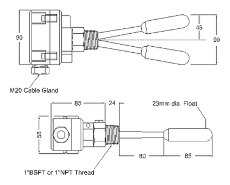
Tip of the arm travels 45 mm each side of horizontal centre. Switching occurs ±2° around horizontal (2 degrees each side of the horizontal centre line), so the arm movement can be confined to within 3 to 4 degrees each side of horizontal and the switch will still operate properly.
Manual Override
All LM-H and LM-L models include a manual override button. Press to switch on regardless of float position — useful for testing and commissioning.
Installation
Install the switch in a tank socket on the side wall of a tank (or riser pipe), in the horizontal plane, with the float arm rising and falling vertically. It needs a minimum of 25 mm of clearance above and below its centre line axis for free movement of the float. The float passes through the inside diameter of a standard pipe thread socket, so the switch can be installed from the outside of the tank. Apply thread tape or sealant to the thread and screw the switch in using the spanner flats on the process adaptor — never by twisting the electrical housing — leaving a gap of approximately 4 mm between the end of the thread and the face of the tank socket. The cable entry must be on the underside of the switch, pointing straight down. Do not install the switch where the pressure is greater than the float rating of 980 kPa (100 metres head) or the liquid temperature is greater than 80 °C. Do not expose it to freezing (lag the tank and switch where low temperatures will be encountered), and do not use it in high temperature applications or in water hotter than 80 °C. The stainless body of the switch is rated to withstand 400 bar pressure; however, the float itself is only designed to withstand 100 metres head pressure (980 kPa or 142 psi).
Wiring and Earthing
The LM level switch is a mains voltage device: all electrical work must be performed by a fully qualified and licensed electrician. Check the part number on the label inside the lid before wiring, and confirm the load is within the electrical ratings — the LM-L switch is easily damaged by overload. The terminals are marked COM (common), NO (normally open) and NC (normally closed); for a two-wire connection use COM plus either NO or NC to suit the application. Connect the earth terminal inside the housing — the LM must be earthed when operated at mains voltage. Fully tighten the cable gland nut, check the lid gasket is in place and tighten the lid down: without its lid the switch is not water, weather or insect proof and presents a shock hazard that may cause death or serious injury.
Hazardous Areas
The LM-H is not certified for use in hazardous areas and must not be installed in any area classified as hazardous under AS/NZS 60079.10 (Zone 0, 1, 2, 20, 21 or 22). The LM-L is simple apparatus under AS/NZS 60079.11 and may be used in a hazardous area only as part of an intrinsically safe circuit, connected through suitably certified associated apparatus. It is not Ex certified in its own right. The associated apparatus must not exceed Uo ≤ 30 V, Io ≤ 100 mA. The full conditions of use are given in the installation sheet.
Replacing the Float Arm
The float arm and its associated pivot bearings are replaceable items. Spare assemblies can be obtained from your supplier — please quote the part number of the level switch when ordering. To remove the assembly, unscrew and remove the locking bolt on the side of the process adaptor (right-hand thread), pull the float arm assembly straight out without twisting it, and thoroughly clean the inside of the process adaptor. Replacement arm assemblies are supplied with new bearing shells and a large retaining O-ring: assemble the two bearing shells onto the arm (O-ring groove towards the long end of the arm), fit the large O-ring, align the flat face and location hole of the bearing shell with the locking bolt hole, and push the assembly all the way in to the dead stop. Check or replace the small O-ring under the locking bolt head, apply silicone grease or Vaseline to the bolt thread, then fit and fully tighten the locking bolt. Test the arm by pushing it up and down: it should swing freely and, when pushed to the up position, drop to the off position under its own weight when released.
Serviceability
Fully field-serviceable. Single externally-accessible screw releases the electrical housing from the wet-end. The float arm and its pivot bearings are replaceable items: spare float arm assemblies are available from your supplier — please quote the part number of the level switch when ordering. Replacement floats, seals and switches available from Kelco Engineering or your distributor.