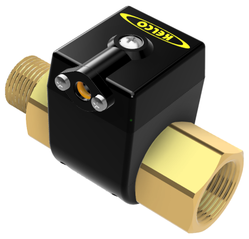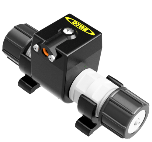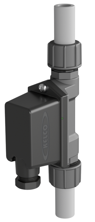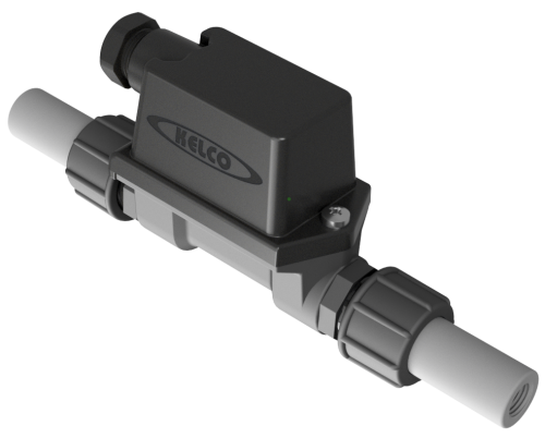
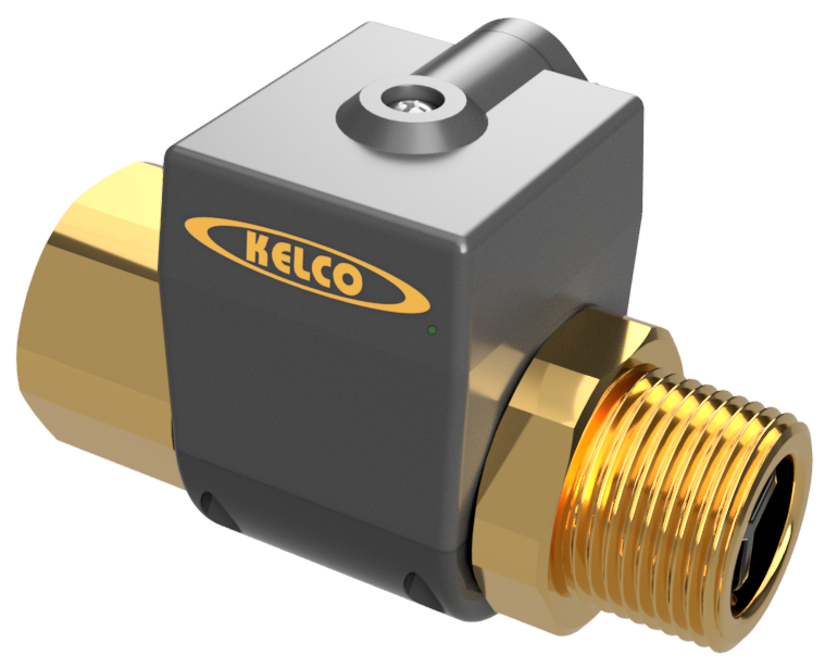
Larger sibling of the C15 — 1″ BSPT/NPT brass body switch for medium-flow applications. Versatile, magnetically actuated, normally-off; switches on in response to flow. Ideal for clean-liquid applications including pressure boosting and the control of pumps or fans via a relay, contactor or PLC — in fresh water, sea water and diesel fuel.
C25 Series
Inline Flow Switches
Features
- One-piece brass body
- All-position mounting
- Diesel- and oil-suited model available
- Dry reed switch contacts
- Detects very low flows: switches on at 0.28 L/min (vertical, non-magnetic retainer)
- Very low head loss
- Fully serviceable
- Weatherproof
The C25 Series is built around the same proven displaced-piston design as the C15 but with a 1″ inlet/outlet for higher flow rates (up to 100 L/min). The sealed electrical module saddles a one-piece brass body and is fully serviceable — it is easily removed without disturbing pipework and can be rotated or reversed independently of the body. Inside the body a free-fitting, magnetically suspended piston actuates the switch as soon as flow starts. The C25 is supplied with dry reed switch contacts for relay or PLC control. The non-magnetic piston retainer (supplied) makes the switch about 6 times more sensitive when mounted vertically with upward flow.
More Information
Select Model
Trade customers should contact sales@kelco.co.nz for account pricing.
Ordering — Available Models
| Model Number | Description |
|---|---|
| C25-B | Dry reed switch S.P.S.T. N.O. — 50 W/VA, 250 VAC / 200 VDC, 1.5 A max. Suitable for PLC, telemetry and logic circuits. |
| C25-B-D | Diesel-suited dry reed switch S.P.S.T. N.O. — 50 W/VA, 250 VAC / 200 VDC, 1.5 A max. Suitable for PLC, telemetry and logic circuits. |
Operating Limitations
| Switching point on rising flow (horizontal or vertical, magnetic retainer fitted) | 1.6 L/min (water at ambient) |
|---|---|
| Switching point on falling flow (horizontal or vertical, magnetic retainer fitted) | 1.3 L/min (water at ambient) |
| Switching point on rising flow (vertical, flow upward, non-magnetic retainer fitted) | 0.28 L/min (water at ambient) |
| Switching point on falling flow (vertical, flow upward, non-magnetic retainer fitted) | 0.20 L/min (water at ambient) |
| Maximum recommended flow rate through switch | 100 L/min |
| Maximum operating pressure (static or dynamic) | 100 bar / 1450 psi |
| Operating temperature range | Hot or cold liquids from −20 °C up to 90 °C continuous; can be steam-sterilised at 100 °C for short periods |
| Ingress protection rating | IP56 |
Electrical Data
| Module type | Dry-contact reed switch (electrical module B) |
|---|---|
| Contact configuration | S.P.S.T. normally open |
| Switched power (maximum) | 50 W/VA |
| Switched voltage (maximum) | 250 VAC / 200 VDC |
| Switched current, resistive AC RMS (maximum) | 1.5 A |
| Inductive loads (power factor 0.4) | Not suitable |
| Rating | 0 to 250 VAC / 200 VDC at 50 W/VA maximum switched power |
| Typical application | PLC, telemetry and relay logic circuits |
Dimensions
Switching-Point Sensitivity
Switching point and sensitivity to flow depend on orientation, liquid velocity, viscosity and piston clearance. With the switch mounted vertically and flow passing upward, fitting the supplied non-magnetic piston retainer makes the C25 approximately 6 times more sensitive (drops switch-on flow from 1.6 L/min to 0.28 L/min). For this the switch must be mounted vertically with the flow switch entry facing downwards, and the piston and retaining components can be changed by removing the stainless steel circlip with long-nose pliers. Switching points are for water at ambient temperature: increasing fluid viscosity decreases the flow rate required to actuate the switch, and decreasing it proportionally increases the switch-on flow rate.
Hazardous Areas
The C25-B and C25-B-D are simple apparatus under AS/NZS 60079.11 and may be used in a hazardous area only as part of an intrinsically safe circuit, connected through suitably certified associated apparatus. They are not Ex certified in their own right. The full conditions of use are given in the installation sheet.
Compatible Liquids and Iron
Suits many clean liquids, including fresh water, sea water and diesel fuel. This flow switch operates magnetically and is therefore not suited to any application where iron or iron scale may be present in the process liquid. Where scale or entrained material may be present, always install a Y-strainer in the inlet pipe directly before the switch.
Installation
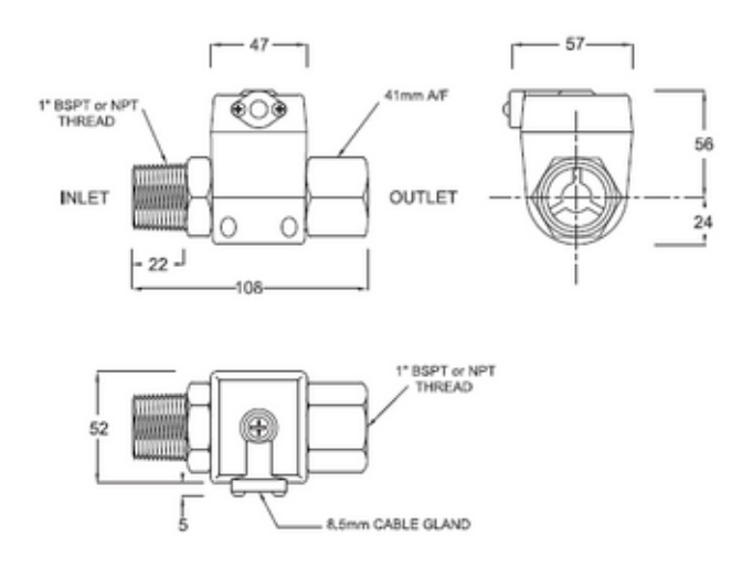
Install in any location in vertical or horizontal pipes; in vertical pipes flow can be upward or downward with very little difference in flow sensitivity. Where possible, fit a union on the inlet and outlet for easy removal for cleaning or servicing, and orient the switch correctly to the direction of flow — the male threaded end is the inlet. Make sure no thread tape or other material enters the switch. The electrical module can be removed or loosened (undo the 4 self-tapping screws and the sealed module lifts off) so the body can be screwed into tight locations, for example the discharge port of a pump.
Check Valves
Many applications benefit from a non-return valve in the pipework directly before the switch. The flow switch is not designed to operate as a one-way valve, and rapid or high pressure flow reversal, such as water hammer, can damage its piston.
Electrical Safety
The C25 Series flow switch is a mains voltage device. All electrical work must be performed by a fully qualified and licensed electrician and conform to AS/NZS (or equivalent) standards and local wiring rules. After installing or servicing, always replace the lid, fully tighten the lid screw and ensure the cable gland is fully tightened. Without its lid the switch is not weather or insect proof and presents a potential shock hazard.
Serviceability
Fully field-serviceable. The electrical module is easily removed without disturbing pipework (undo the 4 self-tapping screws that secure the two halves of the module; the sealed module then lifts off) and can be rotated or reversed independently of the body. The piston should be a free fit and spring back to its off position as soon as flow stops; if it jams, remove the spring circlip in the outlet port with long-nose pliers and clean the piston and its three-finned magnetic spider, checking for iron scale. The C25-B can be tested with a continuity tester: initially off, and on when the piston is pushed back. Spare modules and seal kits available from Kelco Engineering or your distributor.