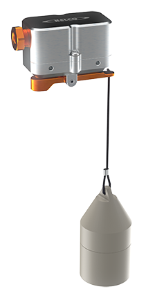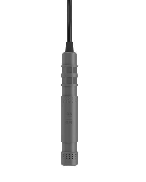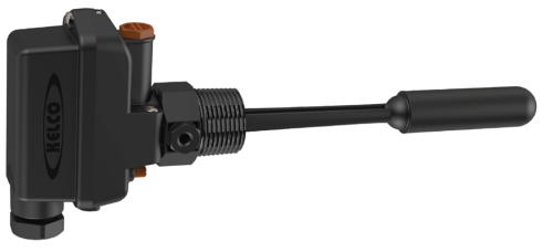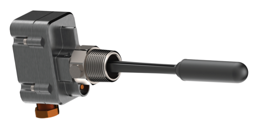
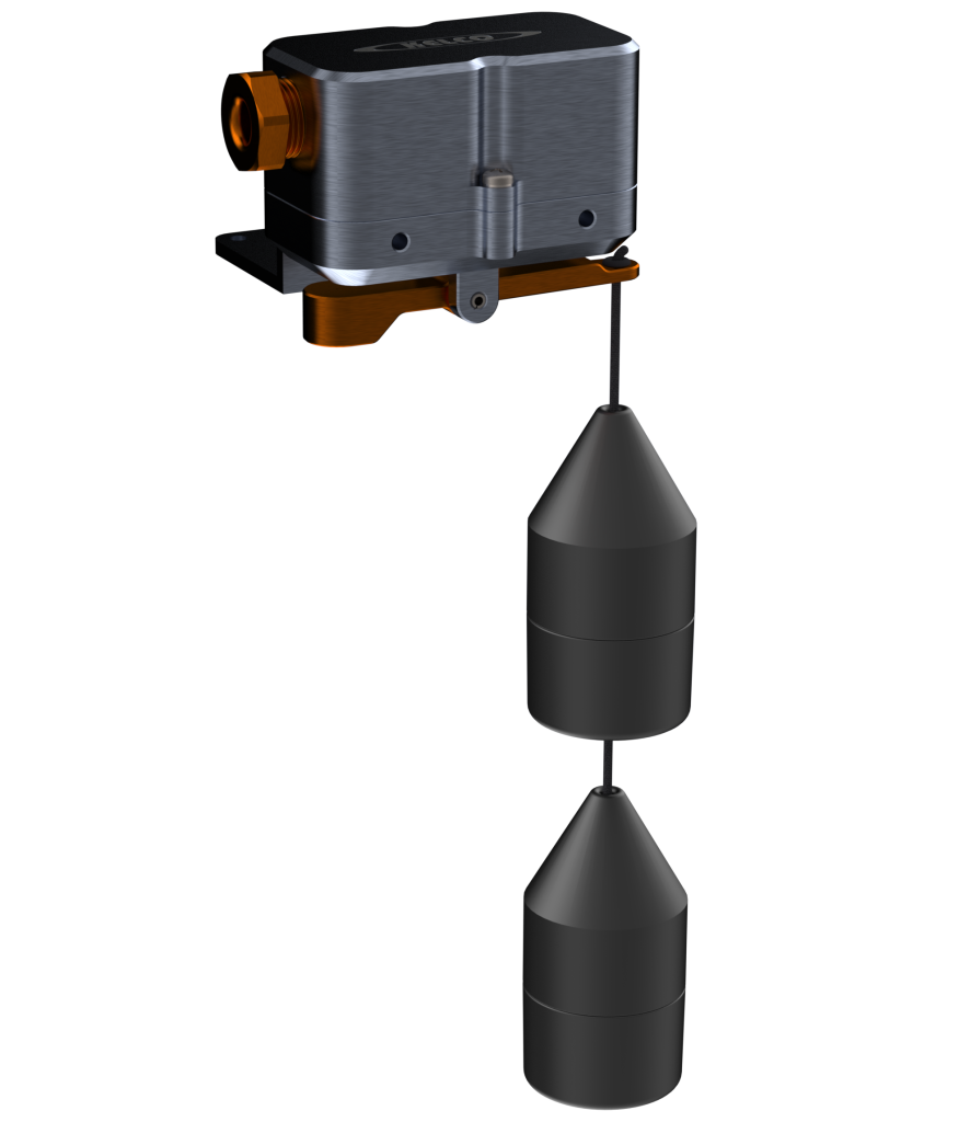
Top entry two-position level regulator on a single suspended cord — two solid twist-lock displacers set the high and low switching points, from a 115 mm minimum to a 20 m maximum level differential. 20 A S.P.D.T. switch rated to 500 VAC (2 HP UL motor rating at 250 VAC) in a heavy-duty all-metal weatherproof housing.
D50 Series
Level Switches
Features
- High and low float level control for tanks and sumps
- 20 A S.P.D.T. switch rated to 500 VAC; 2 HP UL motor rating at 250 VAC
- No metal parts in contact with liquids
- Heavy-duty fully weatherproof all-metal housing
- Super-reliable magnetic action
- Two mounting brackets supplied (wall + right-angle)
- 115 mm minimum level differential (displacers stacked together), up to 20 m maximum level differential
- Twist-lock displacers set the high and low switching points anywhere on the cord
- Maximum liquid temperature 90 °C (displacers and cord)
- Sumps can be pumped out to within 20 mm of the floor
The D50 carries two non-floating glass-reinforced polypropylene displacers on a virgin polypropylene suspension cord (3 m supplied; cords up to 20 m available). Twist-lock the displacers anywhere on the cord to set the high and low switching points (e.g. low at the bottom of a tank, high near the top). A falling level trips when the bottom displacer is partly uncovered; a rising level resets when the top displacer is two-thirds covered. Surface agitation, froth, and floating or submerged solids do not affect the action. The switch can be mounted in any location above the liquid being sensed. Designed to detect a level change in liquids with SG 0.95 to 1.0, that is, water or water that contains dissolved or suspended solids. For fresh water and waste water; not for sea water or chemicals.
Select Model
Trade customers should contact sales@kelco.co.nz for account pricing.
Ordering — Available Models
| Model Number | Description |
|---|---|
| D50 | D50 two-position level switch — two displacers, 3 m of polypropylene cord (up to 20 m available), wall mounting plate and right-angle mounting bracket supplied |
Operating Limitations
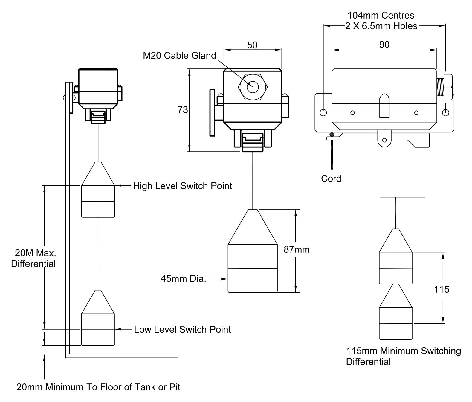
| Minimum level differential | 115 mm with the 2 displacers stacked close together |
|---|---|
| Maximum level differential | 20 metres (3 metres of cord is supplied with the switch) |
| Minimum distance from switch point to floor of a tank or sump | 20 mm (sumps can be pumped out to within 20 mm of the floor) |
| Maximum liquid temperature | 90 °C (displacers and cord only can withstand this temperature) |
| Specific gravity of process liquid | > 0.95 (water at ambient temperature) |
| Ingress protection rating | IP56 and IP68 to 1 metre submergence |
Electrical Data
| Switch type | S.P.D.T. (single pole, double throw) switch, suitable for all general control circuit applications up to 500 VAC. Ideal for the control of pump starters, relay logic circuits, and for the direct control of contactors and timers |
|---|---|
| Switch rating | Rated to 500 VAC: 20 A resistive (15 A at 500 VAC) |
| Motor load rating | Motor load ratings 12.5 A at 125 VAC, 8.3 A at 250 VAC and 2 A at 500 VAC (UL: 1 HP at 125 VAC, 2 HP at 250 VAC) |
| Maximum switched voltage | 500 VAC |
| Maximum switched current | 20 A (15 A at 500 VAC) |
| Resistive load rating (NC and NO) | 20 A at 125 VAC; 20 A at 250 VAC; 15 A at 500 VAC; 20 A at 8 VDC; 20 A at 14 VDC; 6 A at 30 VDC; 0.5 A at 125 VDC; 0.25 A at 250 VDC |
| Lamp load rating | 7.5 A at 125 VAC; 7.5 A at 250 VAC; 4 A at 500 VAC; at 8 VDC, 14 VDC and 30 VDC: 3 A NC / 1.5 A NO; at 125 VDC: 0.5 A NC / 0.5 A NO; at 250 VDC: 0.25 A NC / 0.25 A NO |
| Inductive load rating (NC and NO) | 20 A at 125 VAC; 20 A at 250 VAC; 10 A at 500 VAC; 20 A at 8 VDC; 15 A at 14 VDC; 5 A at 30 VDC; 0.05 A at 125 VDC; 0.03 A at 250 VDC |
| Motor load rating (NC and NO) | 12.5 A at 125 VAC; 8.3 A at 250 VAC; 2 A at 500 VAC; 12.5 A at 8 VDC; 12.5 A at 14 VDC; 5 A at 30 VDC; 0.05 A at 125 VDC; 0.03 A at 250 VDC |
| Contact loading note | Do not apply maximum voltage at maximum current across the switch contacts. See the load ratings above for current limits at specific voltages and for specific loads |
| Terminal identification | COM 1 (common), NC 2 (normally closed), NO 3 (normally open). To pump out of a tank use terminals 1 (COM) and 3 (NO); to pump into a tank use terminals 1 (COM) and 2 (NC) |
| Cable gland | M20 cable gland; cable 10 mm dia. maximum; two cable crimps supplied to suit various cable sizes |
| Earthing | M4 earth screw provided inside the lid |
Dimensions
Typical Applications
Level control in confined or tight locations; pump-in or pump-out applications; water-tank level control; effluent and liquid-waste level control; slurry and high-solids services; fresh water and waste water (not for sea water or chemicals); sumps, pits, bores, tanks, wells or bunds.
Adjustable Switching Points
The displacers are twist-locked onto the cord, so the high and low switching points can be set anywhere along the cord at installation. Set the bottom one near the lowest acceptable level (pump-out cut-off / fill-start), and the top one near the highest acceptable level (overflow alarm / fill-stop). The minimum level differential is 115 mm (displacers stacked close together) and the maximum is 20 metres; 3 m of cord is supplied and cords up to 20 m are available from Kelco or your supplier.
Fitting the Displacers
Assemble each displacer on the cord: thread the cord through the three components, lay it in the trench in the anvil, slide the anvil into the top body half, screw the two body halves together and tie a knot in the free end of the cord. Position the displacers with their conical ends pointing upwards, one at the required high level switching point and one at the low level switching point, then twist and lock them onto the cord. Keep the bottom displacer clear of the floor of the pit or tank, and both displacers well clear of any inlet or outlet pipes and of the floor by at least 20 mm.
Installation and Mounting
A flat mounting plate is supplied for installing the switch against the walls of pits or tanks, plus an angle bracket for mounting on any flat horizontal surface such as tank lids or horizontal bracing. M5 threaded mounting holes in the sides of the switch body let the cable entry point to the right or left. Whichever bracket is used, the top face of the lid must be perfectly horizontal (in both planes) so the cord and displacers hang vertically beneath the switch. The slotted angle bracket suits sloping beams and tank lids and can be inverted if required; fully tighten the 2 × M5 Phillips head screws. Thread the cord through the hole at the end of the actuating arm and tie a double knot in it.
Operating Environment
Controls the level of liquid in wells, tanks, pits, sumps and bores, in potable water, distilled water or water that contains solids, pulp, froth, foam, grit or waste materials. It is not suitable for sea water or chemical solutions. The weatherproof electrical housing is normally mounted above the liquid, with the displacers suspended on the cord at the points where rising or falling levels are to operate the switch. The suspension cord and displacers are the only parts in contact with the liquid and are made from polypropylene.
Exposed Applications
If the switch is mounted in an outside location, for example on top of an open water tank, protect the cord, displacers and electrical lead from direct exposure to the sun. A simple shroud can be made from a length of 50 mm or larger PVC pipe stood on end in the tank, with the D50 mounted so its displacers and cord sit inside the open pipe. The electrical lead can be protected by running it through a length of flexible conduit.
Wiring and Earthing
The D50 is a mains voltage device: all electrical work must be performed by a fully qualified and licensed electrician. To pump out of a tank, use terminals 1 (COM) and 3 (NO). To pump into a tank, use terminals 1 (COM) and 2 (NC). Crimp one of the two supplied cable crimps onto the cable’s outer sheathing at least 5 mm back from its end, pull it hard against the inner wall of the M20 gland, then fully tighten the gland (cable 10 mm dia. maximum). An M4 earth screw is provided inside the lid and all applications should be properly earthed.
Calibration
Each D50 is factory calibrated to operate with the two displacers supplied. If required, re-calibrate using the M3 Allen head stainless grub screw (secured with a lock nut) on the top deck of the switch. If the switch fails to operate on a falling level (does not switch when the falling level uncovers the bottom displacer), unlock the lock nut, turn the calibration screw ¼ turn anti-clockwise, re-lock and test; if it still fails, turn a further ¼ turn anti-clockwise and repeat. If it fails to operate on a rising level (does not switch when the top displacer is covered), unlock the lock nut, turn the screw ¼ turn clockwise, re-tighten and test; if it still fails, turn a further ¼ turn clockwise and repeat.
Hazardous Areas
The D50 is not certified for use in hazardous areas and must not be installed in any area classified as hazardous under AS/NZS 60079.10 (Zone 0, 1, 2, 20, 21 or 22).
Serviceability
Fully field-serviceable. Spare displacers, cord and switch modules available from Kelco Engineering or your distributor.