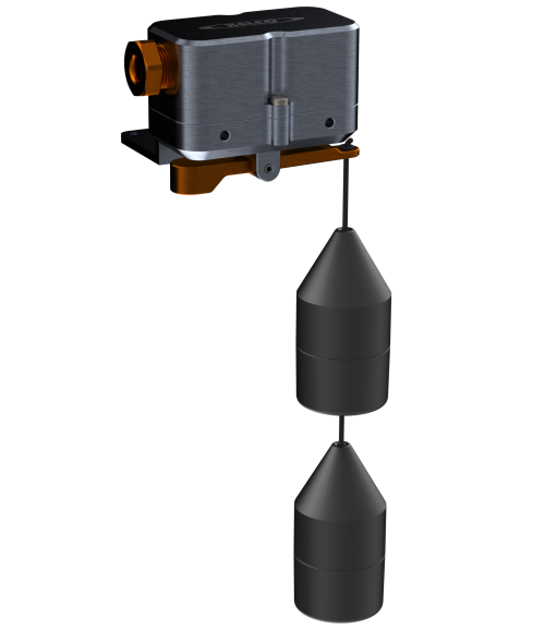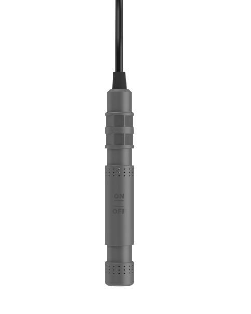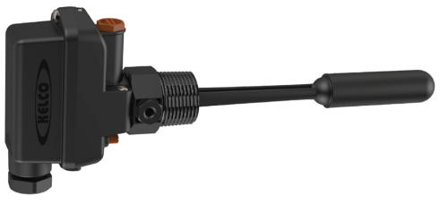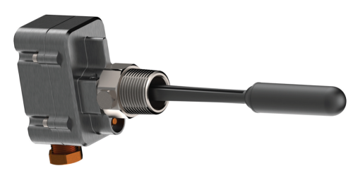
Single-point level switch operating on Archimedes’ principle — a non-floating polypropylene displacer suspended from a billet-aluminium head changes weight as it submerges, actuating a 20 A S.P.D.T. micro-switch (rated to 500 VAC) through a magnetic isolator. No metal parts in contact with liquid, full IP67 housing.
D40 Series
Level Switches
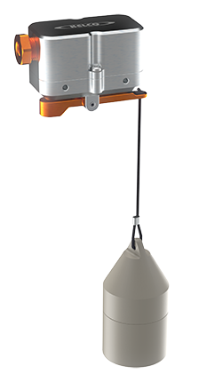
Features
- 20 A S.P.D.T. switch rated to 500 VAC; 2 HP UL motor rating at 250 VAC
- No metal parts in contact with liquids
- 60 mm level change between on and off
- Highly reliable magnetic action
- Fully sealed IP67 electrical housing
- M20 cable gland built in
- Two mounting brackets supplied
- Maximum liquid temperature 90 °C
- Solid billet aluminium electrical head with polypropylene displacer and cord
- Tolerates solids, slurries, pulp, froth, foam and floating scum or debris
The non-floating polypropylene displacer is suspended from the underside of the D40 with polypropylene cord (3 m supplied as standard; up to 20 m available). When the displacer submerges, its weight is reduced by an amount equal to the weight of the liquid displaced — a magnet detects the change and the actuating arm trips the switch through the solid metal wall of the electrical housing. Two mounting brackets supplied (wall mounting plate + angle bracket) for direct mounting on walls, tank lids or horizontal beams. For fresh water and waste water with SG 0.95 or greater; not for sea water or chemicals.
More Information
Select Model
Trade customers should contact sales@kelco.co.nz for account pricing.
Ordering — Available Models
| Model Number | Description |
|---|---|
| D40 | D40 single-point level switch — polypropylene displacer, 3 m of polypropylene cord (up to 20 m available) and two mounting brackets supplied |
Operating Limitations
| Fixed switching differential | 60 mm |
|---|---|
| Maximum distance between D40 and displacer | 20 metres (3 m of cord is supplied as standard) |
| Minimum distance from displacer to the floor of a tank or sump | 20 mm |
| Minimum inside diameter of pipe housing or shroud | 70 mm |
| Maximum liquid temperature | 90 °C |
| Specific gravity of process liquid | 0.95 or greater |
| Ingress protection rating (weatherproof rating) | IP56 and IP68 to 1 metre submergence |
Electrical Data
| Switch type | S.P.D.T. (single pole, double throw) switch, suitable for all general control circuit applications up to 500 VAC. Ideal for the control of pump starters, relay logic circuits, and for the direct control of contactors and timers |
|---|---|
| Switch rating | Rated to 500 VAC: 20 A resistive (15 A at 500 VAC) |
| Motor load rating | Motor load ratings 12.5 A at 125 VAC, 8.3 A at 250 VAC and 2 A at 500 VAC (UL: 1 HP at 125 VAC, 2 HP at 250 VAC) |
| Maximum switched voltage | 500 VAC |
| Maximum switched current | 20 A (15 A at 500 VAC) |
| Resistive load rating (NC and NO) | 20 A at 125 VAC; 20 A at 250 VAC; 15 A at 500 VAC; 20 A at 8 VDC; 20 A at 14 VDC; 6 A at 30 VDC; 0.5 A at 125 VDC; 0.25 A at 250 VDC |
| Lamp load rating | 7.5 A at 125 VAC; 7.5 A at 250 VAC; 4 A at 500 VAC; at 8 VDC, 14 VDC and 30 VDC: 3 A NC / 1.5 A NO; at 125 VDC: 0.5 A NC / 0.5 A NO; at 250 VDC: 0.25 A NC / 0.25 A NO |
| Inductive load rating (NC and NO) | 20 A at 125 VAC; 20 A at 250 VAC; 10 A at 500 VAC; 20 A at 8 VDC; 15 A at 14 VDC; 5 A at 30 VDC; 0.05 A at 125 VDC; 0.03 A at 250 VDC |
| Motor load rating (NC and NO) | 12.5 A at 125 VAC; 8.3 A at 250 VAC; 2 A at 500 VAC; 12.5 A at 8 VDC; 12.5 A at 14 VDC; 5 A at 30 VDC; 0.05 A at 125 VDC; 0.03 A at 250 VDC |
| Contact loading note | Do not apply maximum voltage at maximum current across the switch contacts. See the load ratings above for current limits at specific voltages and for specific loads |
| Terminal identification | COM 1 (common), NC 2 (normally closed), NO 3 (normally open) |
| Cable gland | M20 cable gland; cable 10 mm dia. maximum; two cable crimps supplied to suit various cable sizes |
| Earthing | M4 earth screw provided inside the lid |
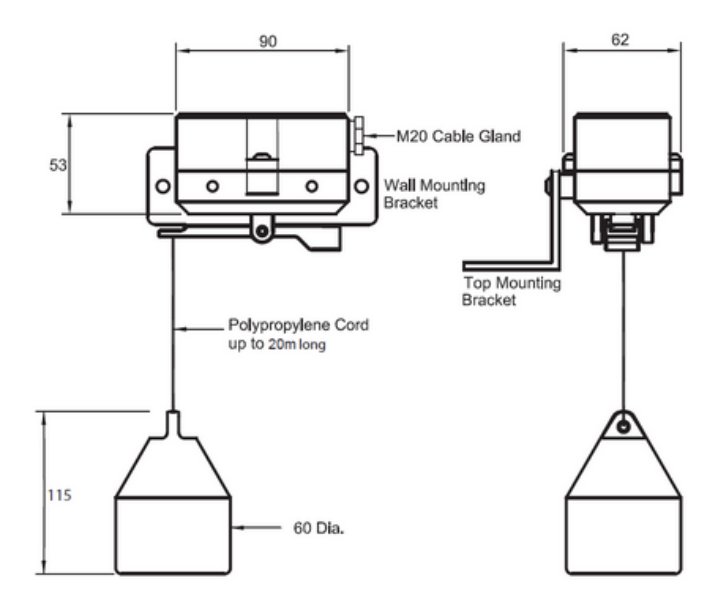
Dimensions
Typical Applications
Confined locations in sumps and pits; bund-area warning alarms; cooling-tower water-level control; effluent and high-solids uses; fresh water and waste water (not for sea water or chemicals); level monitoring in wells and bores.
SG Sensitivity
Designed for liquids with specific gravity 0.95 or greater (water, water-based effluent, slurries). Because it is the change of weight sensed by the displacer as it submerges that actuates the switch, the specific gravity of the liquid directly affects operation. The D40 will only operate in liquids with an SG of 0.95 or greater; it will not operate in liquids with an SG below 0.95.
Installation and Mounting
A flat mounting plate is supplied for installing the switch against the walls of pits or tanks, plus an angle bracket for mounting on any flat horizontal surface such as tank lids or horizontal bracing. M5 threaded mounting holes in the sides of the switch body let the cable entry point to the right or left. Whichever bracket is used, the top face of the lid must be perfectly horizontal (in both planes) so the cord and displacer hang vertically beneath the switch. The slotted angle bracket suits sloping beams and tank lids and can be inverted if required; fully tighten the 2 × M5 Phillips head screws. Thread the cord through the hole at the end of the actuating arm and tie a double knot in it, then tie the free end through the hole in the top of the displacer.
Operating Environment
Detects liquid level in wells, tanks, pits, sumps, bores and bund areas. It is designed for fresh water and waste water and is not suitable for sea water or chemical solutions. Highly tolerant of liquids containing solids, slurries or pulp, and works reliably in froth or foam and where floating scum or debris is present. A solid metal wall separates the electrical enclosure from the actuating arm, so the housing is totally sealed and weatherproof provided the lid is fully tightened and the cable gland is properly used. The polypropylene cord and displacer are the only parts in contact with the process liquid.
Warm Liquids
Ideal for warm liquid applications (maximum liquid temperature 90 °C) provided the electrical head is mounted well above the liquid and is protected from hot vapour. The wetted cord and displacer are highly tolerant of liquids at elevated temperatures.
Wiring and Earthing
The D40 is a mains voltage device: all electrical work must be performed by a fully qualified and licensed electrician. To switch ON when a rising water level covers the displacer, use terminals 1 (COM) and 3 (NO). To switch ON when a falling water level uncovers the displacer, use terminals 1 (COM) and 2 (NC). Crimp one of the two supplied cable crimps onto the cable’s outer sheathing at least 5 mm back from its end, pull it hard against the inner wall of the M20 gland, then fully tighten the gland (cable 10 mm dia. maximum). An M4 earth screw is provided inside the lid and all applications should be properly earthed.
Calibration
Each D40 is factory calibrated to operate with the displacer supplied. If required, re-calibrate using the M3 Allen head stainless grub screw (secured with a lock nut) on the top deck of the switch. Switching must occur within the length of the single displacer: correctly adjusted, the switch changes state at the bottom edge of the conical section on a rising level and at the seam line halfway down the straight section on a falling level. If a rising level fails to actuate the switch with the displacer fully submerged, turn the calibration screw clockwise in ¼ turn steps until it operates at the correct point. If it fails to operate on a falling level, turn the screw anti-clockwise ¼ turn and retest, repeating if required.
Hazardous Areas
The D40 is not certified for use in hazardous areas and must not be installed in any area classified as hazardous under AS/NZS 60079.10 (Zone 0, 1, 2, 20, 21 or 22).
Serviceability
Fully field-serviceable. Replacement displacer, cord and switch available from Kelco Engineering or your distributor.