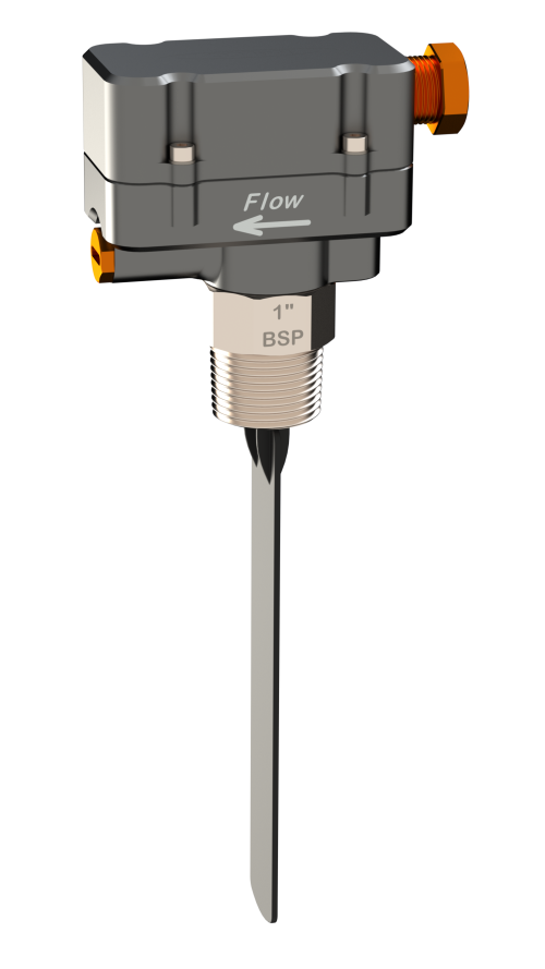
Tough, highly-sensitive paddle switch for both hot and cold liquids. Magnetic repulsion drive (no seals, diaphragms or bellows) gives a high-pressure switch with no points of potential failure. Polypropylene or 316 stainless process connection; 3/4″ or 1″ BSP/NPT.
F Series
Paddle Flow Switches
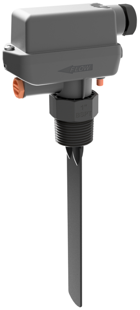
Features
- 5–500 V AC, 15 A S.P.D.T. switch (F-H model)
- Low-voltage gold-contact ‘L’ model available (F-L)
- Low-voltage reed-switch model also available (F-RL)
- Polypropylene or 316 stainless models
- Switches available with 3/4″ and 1″ BSP & NPT threads
- Manual override built in (F-H and F-L models)
- Modular construction — remove the housing, or unscrew the switch from the pipework, without disturbing the wiring
- High-pressure 400 bar / 5800 psi models available (stainless)
- Seal-less magnetic drive
- Weatherproof IP67 housing
- Easily serviceable
The electrical housing is a separate assembly that locks onto the wet end with a single, externally accessible screw, so it can be removed for servicing — or the switch unscrewed from the pipework — without disturbing the wiring. Every F Series switch is supplied with a glass-fibre-reinforced polypropylene paddle that can be cut and shaped to suit pipework 25 mm (1″) and larger. A built-in manual override switches the unit on at the press of a button, regardless of flow, so pumps can be started manually at any time and testing and commissioning are simple. Available with a polypropylene or a 316 stainless steel high-pressure process connection, with models to suit most applications, including seawater, bore water, acids, alkalis and many chemical solutions.
Trade customers should contact sales@kelco.co.nz for account pricing.
Ordering — Available Models
| Model Number | Description |
|---|---|
| F-H-20B-SS | Standard heavy-duty S.P.D.T. switch (H), 3/4" BSP thread, high-pressure 316 stainless steel process connection + polypropylene paddle (3/4" is stainless only; no polypropylene 20 mm option) |
| F-H-20N-SS | Standard heavy-duty S.P.D.T. switch (H), 3/4" NPT thread, high-pressure 316 stainless steel process connection + polypropylene paddle (3/4" is stainless only; no polypropylene 20 mm option) |
| F-H-25B | Standard heavy-duty S.P.D.T. switch (H), 1" BSP thread, all polypropylene wetted parts |
| F-H-25B-SS | Standard heavy-duty S.P.D.T. switch (H), 1" BSP thread, high-pressure 316 stainless steel process connection + polypropylene paddle |
| F-H-25N | Standard heavy-duty S.P.D.T. switch (H), 1" NPT thread, all polypropylene wetted parts |
| F-H-25N-SS | Standard heavy-duty S.P.D.T. switch (H), 1" NPT thread, high-pressure 316 stainless steel process connection + polypropylene paddle |
| F-L-20B-SS | Low-voltage gold-contact model (L) — S.P.D.T. switch with gold contacts, 3/4" BSP thread, high-pressure 316 stainless steel process connection + polypropylene paddle (3/4" is stainless only; no polypropylene 20 mm option) |
| F-L-20N-SS | Low-voltage gold-contact model (L) — S.P.D.T. switch with gold contacts, 3/4" NPT thread, high-pressure 316 stainless steel process connection + polypropylene paddle (3/4" is stainless only; no polypropylene 20 mm option) |
| F-L-25B | Low-voltage gold-contact model (L) — S.P.D.T. switch with gold contacts, 1" BSP thread, all polypropylene wetted parts |
| F-L-25B-SS | Low-voltage gold-contact model (L) — S.P.D.T. switch with gold contacts, 1" BSP thread, high-pressure 316 stainless steel process connection + polypropylene paddle |
| F-L-25N | Low-voltage gold-contact model (L) — S.P.D.T. switch with gold contacts, 1" NPT thread, all polypropylene wetted parts |
| F-L-25N-SS | Low-voltage gold-contact model (L) — S.P.D.T. switch with gold contacts, 1" NPT thread, high-pressure 316 stainless steel process connection + polypropylene paddle |
| F-RL-20B-SS | Low-voltage reed-switch model, 3/4" BSP, 316 stainless process connection (being phased out: replaced by the F-L) |
| F-RL-20N-SS | Low-voltage reed-switch model, 3/4" NPT, 316 stainless process connection (being phased out: replaced by the F-L) |
| F-RL-25B | Low-voltage reed-switch model, 1" BSP, all polypropylene (being phased out: replaced by the F-L) |
| F-RL-25B-SS | Low-voltage reed-switch model, 1" BSP, 316 stainless process connection (being phased out: replaced by the F-L) |
| F-RL-25N | Low-voltage reed-switch model, 1" NPT, all polypropylene (being phased out: replaced by the F-L) |
| F-RL-25N-SS | Low-voltage reed-switch model, 1" NPT, 316 stainless process connection (being phased out: replaced by the F-L) |
Operating Limitations
| Maximum operating pressure (all-polypropylene model, ambient) | 18 bar / 261 psi (de-rate linearly with temperature — at 60 °C / 140 °F the maximum permissible pressure does not exceed 1 bar / 15 psi absolute) |
|---|---|
| Maximum operating pressure (stainless steel model, ambient) | 400 bar / 5800 psi |
| Minimum burst pressure (all-polypropylene) | 45 bar / 652 psi |
| Minimum burst pressure (stainless steel) | 500 bar / 7215 psi |
| Maximum operating temperature (all-polypropylene) | 60 °C / 140 °F (see pressure de-rating note) |
| Maximum operating temperature (stainless steel) | 80 °C / 176 °F |
| Minimum operating temperature (both models) | -20 °C / -4 °F |
| Ingress protection rating | IP67 |
Electrical Data
| F-H switch type | S.P.D.T. (single pole, double throw) microswitch for general control circuits up to 500 V AC — use at any voltage from 5 to 500 V AC (minimum load 160 mA at 5 V DC). Absolute limits: 500 V AC maximum; 15 A maximum (10 A at 500 V AC). Maximum voltage and maximum current cannot be applied together. |
|---|---|
| F-H typical applications | Pump starters, relay logic, contactors and timers |
| F-H resistive load rating (NC / NO) | 15 A at 125 V AC and 250 V AC; 10 A at 500 V AC; 15 A at 8 V DC and 14 V DC; 6 A at 30 V DC; 0.5 A at 125 V DC; 0.25 A at 250 V DC |
| F-H lamp load rating (NC / NO) | 3 A / 1.5 A at 125 V AC; 2.5 A / 1.25 A at 250 V AC; 1.5 A / 0.75 A at 500 V AC; 3 A / 1.5 A at 8, 14 and 30 V DC; 0.5 A / 0.5 A at 125 V DC; 0.25 A / 0.25 A at 250 V DC |
| F-H inductive load rating (NC / NO) | 15 A at 125 V AC and 250 V AC; 6 A at 500 V AC; 15 A at 8 V DC; 10 A at 14 V DC; 5 A at 30 V DC; 0.05 A at 125 V DC; 0.03 A at 250 V DC |
| F-H motor load rating (NC / NO) | 5 A / 2.5 A at 125 V AC; 3 A / 1.5 A at 250 V AC; 1.5 A / 0.75 A at 500 V AC; 5 A / 2.5 A at 8, 14 and 30 V DC; 0.05 A / 0.05 A at 125 V DC; 0.03 A / 0.03 A at 250 V DC |
| F-H direct motor control | Directly switches pump motors up to 1/4 HP (approx. 185 W) at 240 V AC. For larger motors use a contactor or relay. |
| F-RL switch type | Dry-contact reed switch S.P.D.T. break-before-make — 20 W / VA max, 140 V AC / 150 V DC, 1 A max, 200 V breakdown |
| F-RL typical applications | PLC input, telemetry signaling, low-voltage relay logic |
| F-L switch type | Gold contact microswitch, S.P.D.T., gold alloy contacts, so it switches reliably at the low wetting currents of PLC inputs, telemetry and relay logic. Not suitable for inductive or capacitive loads such as contactors and relays. Loads above the rating will damage the switch. |
| F-L rated current (resistive) | 0.1 A at 125 VAC; 0.1 A at 8, 14 and 30 VDC |
| F-L inrush current | 0.1 A maximum (NC and NO) |
| F-L minimum applicable load | 1 mA at 5 VDC |
| F-L operating range (micro load) | 5 to 30 V, 5 to 800 mW (26 mA maximum at 30 V) |
| F-L contact resistance | 50 mΩ maximum (initial) |
| F-L typical applications | PLC, telemetry and low voltage control |
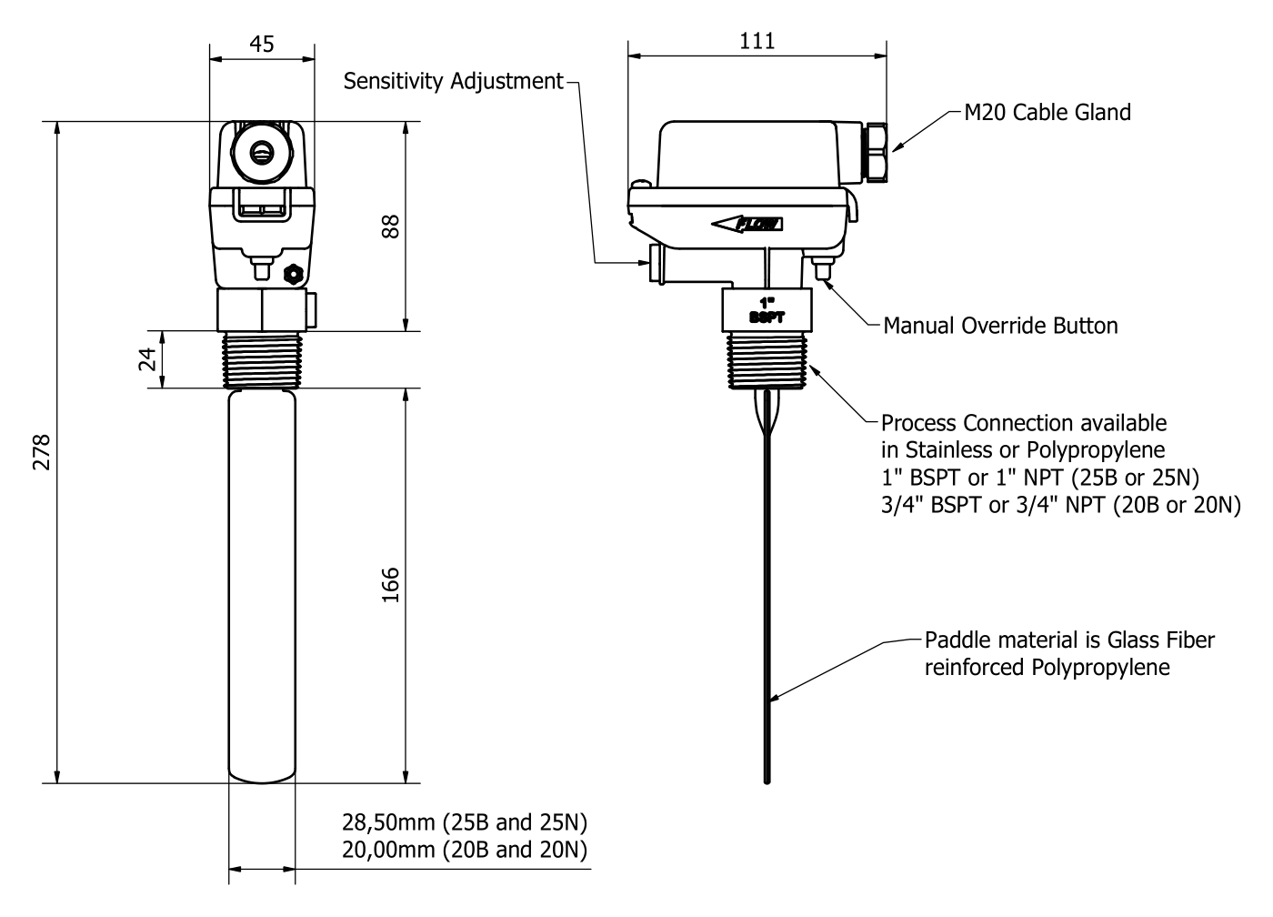
Dimensions
Manual Override (F-H and F-L models)
All F-H and F-L models include a red manual override button on the side of the housing, under the cable gland. Pressing the button switches the flow switch on regardless of flow — useful for manually starting pumps in spite of an initial lack of flow, and for testing/commissioning of control circuits. After wiring, press it to test: the switch changes state as if liquid were pushing the paddle.
Flow Sensitivity & Paddle Trimming
The flow rate needed to actuate the F Series depends on many variables — turbulence, liquid viscosity and the exact area of the paddle face exposed to flow. Trim the paddle with a hacksaw or tin snips so it clears the pipe wall by at least 4 mm all round. As a guide: low flow — paddle just clears the bottom of the pipe; unknown flow — 3/4 of the way across the pipe; high flow — 1/4 to 1/2 of the way across the pipe. Spare paddles are available if too much is cut off. For an accurate estimate of switch performance and to determine the effect of paddle trimming, use the online Paddle Calculator — enter your pipe inside diameter, flow rate and liquid.
Sensitivity Adjustment
F-H and F-L switches are supplied at maximum sensitivity (adjuster wound fully in). To decrease sensitivity, remove the red dust cap and wind the adjusting screw out (anticlockwise) with a wide flat screwdriver. The further out the screw, the more flow is needed to operate the switch. Refit the dust cap.
Mounting
The switch can go in suction or delivery pipework, horizontal or vertical. In vertical pipe the flow must be upward. Do not mount on the underside of horizontal pipe. Where possible, mount the switch away from pumps, valves and bends — a fitting directly upstream makes the flow uneven and turbulent at the paddle, which can shift the switching point slightly or make the paddle flutter near the switching point; downstream fittings have little effect. Mount in a pipe tee, tapping saddle or weld-on socket, square to the flow so liquid hits the flat face of the paddle, with the arrow on the switch pointing in the direction of flow. Seal the thread with PTFE tape or thread sealant, leaving at least 4 mm of thread above the socket, and tighten with a spanner on the spanner flats only — never twist the switch body.
Electrical Installation
The F Series is a mains voltage device — all electrical work must be carried out by a licensed electrician. Terminals are marked C (common), NO (normally open) and NC (normally closed); for a two-wire connection use C plus either NO or NC to suit the application. After wiring, fully tighten the cable gland nut, check the lid gasket is in place and tighten the lid down. Without its lid the switch is not water, weather or insect proof and presents a shock hazard.
Hazardous Areas
The F-H is not certified for use in hazardous areas and must not be installed in any area classified as hazardous under AS/NZS 60079.10 (Zone 0, 1, 2, 20, 21 or 22). The F-L is simple apparatus under AS/NZS 60079.11 and may be used in a hazardous area only as part of an intrinsically safe circuit, connected through suitably certified associated apparatus. It is not Ex certified in its own right. The associated apparatus must not exceed Uo ≤ 30 V, Io ≤ 100 mA. The full conditions of use are given in the installation sheet.
F-L — Inductive and Capacitive Loads NOT Suitable
The F-L is not suitable for inductive or capacitive loads such as contactors and relays. Loads above the rating will damage the switch.
Reed Switch — Inductive Loads NOT Suitable
The F-RL reed switch must NOT be used with inductive loads such as contactors or high-wattage relays. Use the F-H model or interpose a relay/contactor for such applications.
Materials & Chemical Compatibility
All-polypropylene models (no suffix) have polypropylene wetted parts. The -SS models have a high-pressure 316 stainless steel process connection and a polypropylene paddle. The paddle on every F Series model is glass-fibre-reinforced polypropylene. Check that the switch materials suit the liquid being monitored.
20 mm models stainless only
20 mm (3/4″) fittings are only available with the 316 stainless steel process connection — not available in all-polypropylene.
Approved Standards
The ‘H’ and ‘L’ microswitches used in the F Series are approved to UL1054 (File E41515), CSA C22.2 No.55 (File LR21642) and EN61058-1, and are CE marked.
Serviceability
Fully field-serviceable. A single externally accessible screw releases the electrical housing from the wet end — remove it for servicing, or unscrew the switch from the pipework, without disturbing the wiring. Replacement paddles, seals and switches available from Kelco Engineering or your distributor.