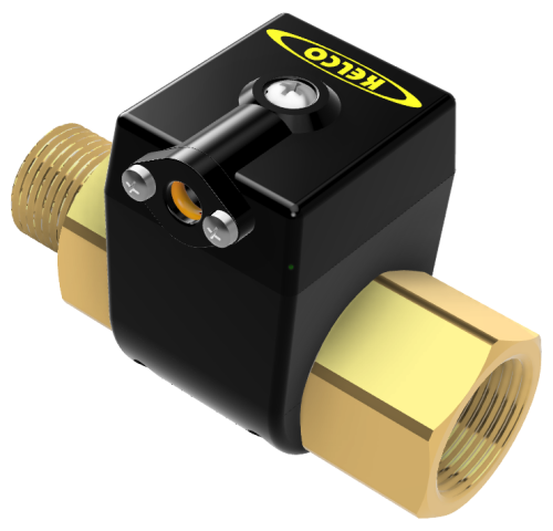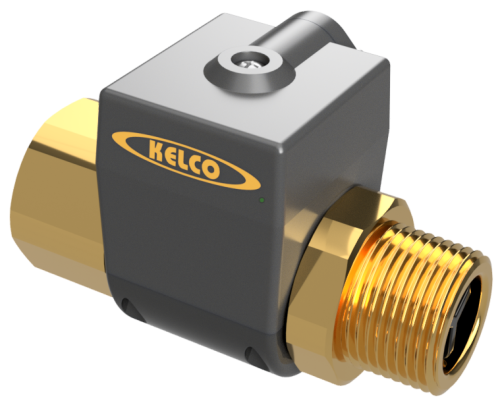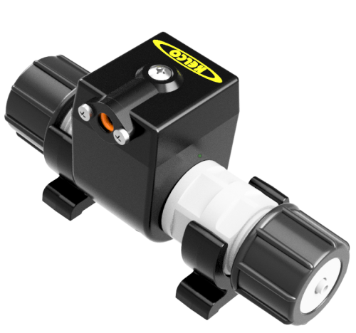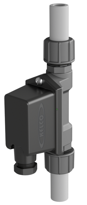
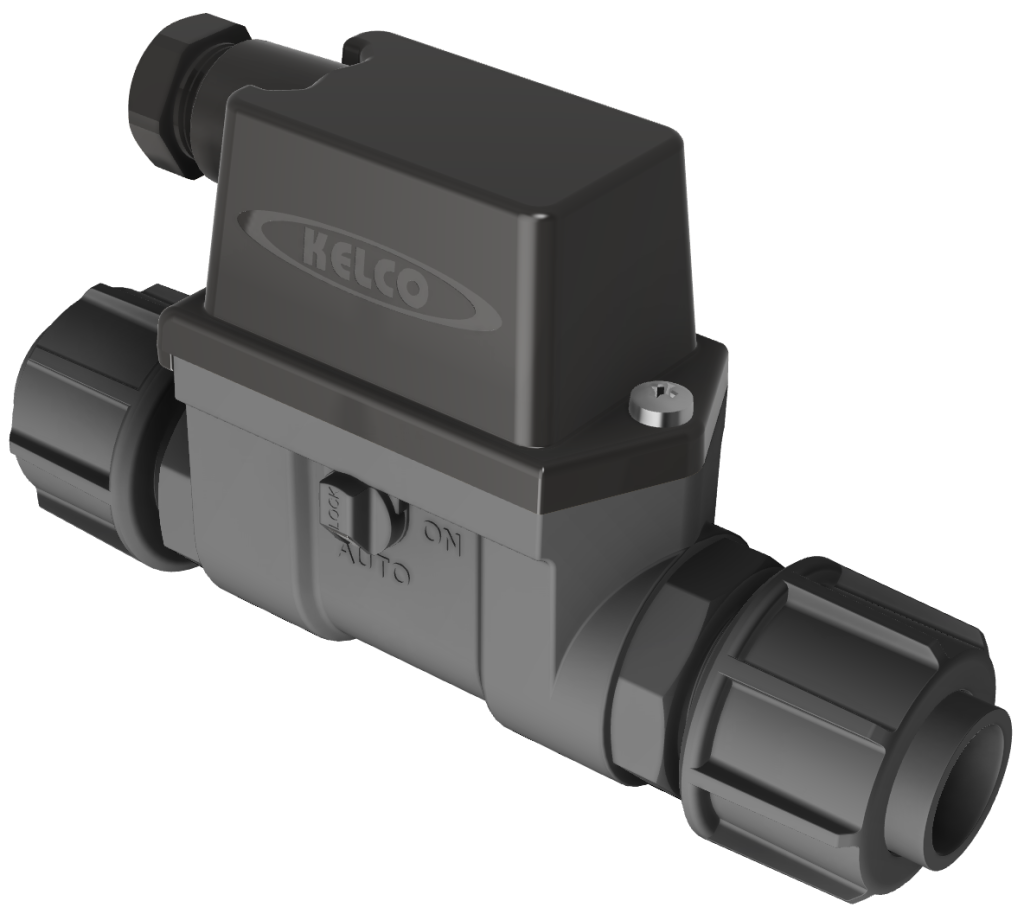
Rugged all-position flow switch for liquids in 15 mm to 25 mm (1/2″ to 1″) diameter pipes — up to 100 L/min. Detects continuous or pulsed flows; no metal parts in contact with the liquid. The P25-S model includes a heavy-duty mechanical switch + manual override for direct control of pump motors (motor load 8.3 A at 250 VAC, UL 2 HP).
P25 Series
Inline Flow Switches
Features
- Directly controls pump motors (P25-S model): motor load 8.3 A at 250 VAC, UL 2 HP
- Ideal for PLC and relay logic
- Manual override available (P25-S model)
- Suits pipes 15 mm to 25 mm (1/2″ to 1″) diameter
- No metal parts in contact with liquids
- 100 L/min maximum flow rating
- Versatile all-position mounting
- 18 bar (260 psi) pressure rating
- IP67 weatherproof housing
- Detects very low flows
The P25 ships with unions and standard PVC pipe sockets for direct solvent-gluing into PVC pipework. With no metal wetted parts it suits aggressive media including ground water, sea water, acids and alkalis. It is made from glass reinforced polypropylene with nitrile O-rings and is suitable for all outdoor exposed applications. Three electrical configurations: P25-B (reed switch, PLC use), P25-C (S.P.D.T. break before make reed, more sensitive), and P25-S (heavy-duty mechanical S.P.D.T. with manual override, direct motor control).
Select Model
Trade customers should contact sales@kelco.co.nz for account pricing.
Ordering — Available Models
| Model Number | Description |
|---|---|
| P25-B-15 | Dry contact reed switch S.P.S.T. normally open — 50 W, 250 V AC / 200 V DC, 1.5 A max. Not suitable for inductive loads. PLC, telemetry and relay-logic circuits. 15 NB PVC sockets to suit pressure pipe. |
| P25-B-20 | Dry contact reed switch S.P.S.T. normally open — 50 W, 250 V AC / 200 V DC, 1.5 A max. Not suitable for inductive loads. PLC, telemetry and relay-logic circuits. 20 NB PVC sockets to suit pressure pipe. |
| P25-B-25 | Dry contact reed switch S.P.S.T. normally open — 50 W, 250 V AC / 200 V DC, 1.5 A max. Not suitable for inductive loads. PLC, telemetry and relay-logic circuits. 25 NB PVC sockets to suit pressure pipe. |
| P25-C-15 | Dry contact reed switch S.P.D.T. break before make — 20 W, 140 V AC / 150 V DC, 1 A max. Not suitable for inductive loads. Higher sensitivity (3 L/min on rising flow). PLC, telemetry and relay-logic circuits. 15 NB PVC sockets to suit pressure pipe. |
| P25-C-20 | Dry contact reed switch S.P.D.T. break before make — 20 W, 140 V AC / 150 V DC, 1 A max. Not suitable for inductive loads. Higher sensitivity (3 L/min on rising flow). PLC, telemetry and relay-logic circuits. 20 NB PVC sockets to suit pressure pipe. |
| P25-C-25 | Dry contact reed switch S.P.D.T. break before make — 20 W, 140 V AC / 150 V DC, 1 A max. Not suitable for inductive loads. Higher sensitivity (3 L/min on rising flow). PLC, telemetry and relay-logic circuits. 25 NB PVC sockets to suit pressure pipe. |
| P25-S-15 | Heavy-duty mechanical S.P.D.T. switch with manual override — 2 HP (UL), 500 V AC / 250 V DC, 20 A at 250 V AC, motor load 8.3 A at 250 V AC. Direct motor control and AC control circuits. 15 NB PVC sockets to suit pressure pipe. |
| P25-S-20 | Heavy-duty mechanical S.P.D.T. switch with manual override — 2 HP (UL), 500 V AC / 250 V DC, 20 A at 250 V AC, motor load 8.3 A at 250 V AC. Direct motor control and AC control circuits. 20 NB PVC sockets to suit pressure pipe. |
| P25-S-25 | Heavy-duty mechanical S.P.D.T. switch with manual override — 2 HP (UL), 500 V AC / 250 V DC, 20 A at 250 V AC, motor load 8.3 A at 250 V AC. Direct motor control and AC control circuits. 25 NB PVC sockets to suit pressure pipe. |
Operating Limitations
| Switching point on rising flow (P25-B / P25-S) | 9 L/min (water at ambient) |
|---|---|
| Switching point on falling flow (P25-B / P25-S) | 7 L/min (water at ambient) |
| Switching point on rising flow (P25-C) | 3 L/min (water at ambient) |
| Switching point on falling flow (P25-C) | 2.5 L/min (water at ambient) |
| Electrical response time (cessation of flow) | 0.1 seconds |
| Maximum recommended continuous flow rate | 100 L/min (head loss across the switch < 50 kPa at 100 L/min) |
| Maximum operating pressure (static or dynamic, ambient) | 18 bar / 260 psi |
| Minimum burst pressure (ambient) | 60 bar / 865 psi |
| Maximum liquid temperature | 60 °C |
| Minimum liquid temperature | -20 °C |
| Liquid pH range | 1 to 14 |
| Ingress protection rating | IP67 |
| Head loss example (water at ambient) | 10 kPa at 40 L/min |
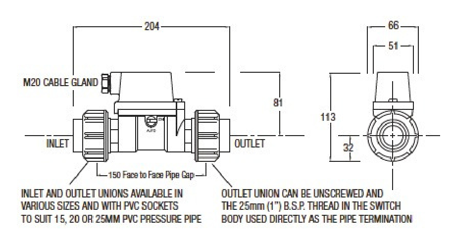
Dimensions
Warning: Electrical Safety
The P25 Series flow switch is a mains voltage device. Death or serious injury may result if this switch is not correctly installed and operated. All electrical work on this switch must be performed by a fully qualified and licensed electrician.
Manual Override (P25-S only)
The P25-S has a manual override located on the side of the switch body under a locking cap (remove the cap by placing a small screwdriver in the notch on its underside; it pops off when lifted gently). The override dial turns through 90 degrees between ‘Auto’ and ‘ON’. Normally left in the ‘Auto’ position; in the ‘ON’ position the state of flow is ignored and the switch is on — useful for priming pumps in spite of an initial lack of flow, or for testing control wiring and simulating switch operation during installation and commissioning. The P25-B and P25-C models do not have manual override.
Direct Motor Control (P25-S only)
The P25-S’s heavy-duty mechanical switch is designed for the direct control of single-phase pump motors (motor load 8.3 A at 250 V AC, UL 2 HP) and suits general control circuits up to 500 V AC (20 A at 250 V AC). For larger motors or 3-phase, drive an interposing contactor and verify cable / voltage drop with the Pump Controller Power Calculator.
Pipe Connection
Inlet and outlet unions are available in various sizes and with PVC sockets to suit 15, 20 or 25 mm PVC pressure pipe (model suffix 15, 20 or 25 = 15NB, 20NB, 25NB). The outlet union can also be unscrewed and the 25 mm (1″) B.S.P. thread in the switch body used directly as the pipe termination.
Mounting & Installation
The P25 can be mounted in any orientation, including upside down. There is a direction of flow arrow on the switch body; the switch will not operate against a reverse flow. Pipework can be used to support the switch, or the switch can be connected directly to valve manifolds or pump ports. Do not use this flow switch as a non-return valve. Protect the switch from freezing and from exposure to hot liquids > 60 °C, do not use it where the static or dynamic pressure exceeds 18 bar, and take care that it is not exposed to water hammer.
Clean Fluid & Line Strainer
The P25 contains a close fitting piston and should only be used where the process fluid is clean and free from entrained or suspended materials. Solutions that contain large particulates, ferrous materials or fibrous matter should not be used in this switch. If the degree of contamination of the process liquid can’t be guaranteed, install a suitable line strainer before the flow switch.
Hazardous Areas
The P25-B and P25-C are simple apparatus under AS/NZS 60079.11 and may be used in a hazardous area only as part of an intrinsically safe circuit, connected through suitably certified associated apparatus. They are not Ex certified in their own right. The full conditions of use are given in the installation sheet. The P25-S is not certified for use in hazardous areas and must not be installed in any area classified as hazardous under AS/NZS 60079.10 (Zone 0, 1, 2, 20, 21 or 22).
Reed Switch Protection (P25-B and P25-C)
The P25-B and P25-C use a dry contact reed switch as the primary switching element. Reed switches offer an operating life in excess of 100 million cycles; however, care needs to be taken to ensure they are not electrically overloaded. If applied in questionable applications, suitable protection should be added to the control circuit. Details of reed switch protection circuits are on our Reed Switch Information page.
Electrical Installation
The P25-S contains a magnetically coupled, high current, high voltage single pole double throw microswitch suited to most general-purpose control circuit applications at any voltage up to 500 VAC; its terminals are Common (1), Normally closed (2) and Normally open (3). The P25-B and P25-C contain a gas-filled reed switch giving an S.P.S.T. or S.P.D.T. break before make action for low power applications. The model number is on a label inside the switch lid. The cable gland is threaded M20 and accepts standard M20 conduit bushes as well as flexible cable. Ensure the lid and cable gland are securely tightened, and in fully exposed locations use secondary precautions such as cable drip loops so that no water can enter the switch housing.
Typical Applications
Safety shower alarms, loss of prime protection for pumps, flow monitor for large dosing systems, constant pressure pump control, control of tank filling systems and low yield bore pump protection.
Serviceability
Fully field-serviceable. Inlet and outlet unions are interchangeable and available in multiple pipe sizes. Spare seals and switch modules available from Kelco Engineering or your distributor.