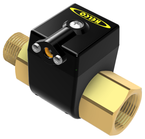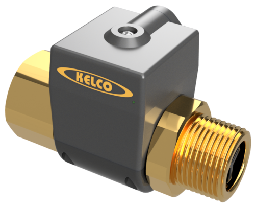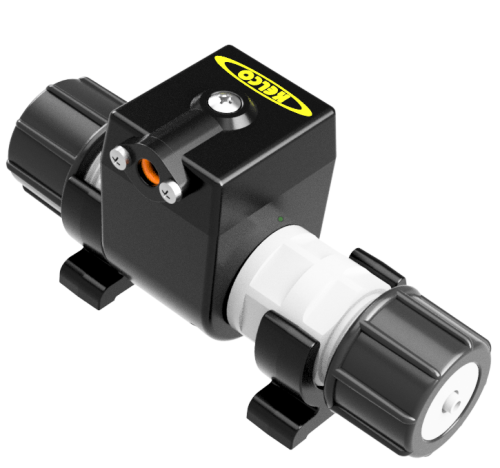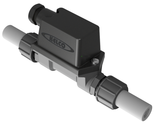
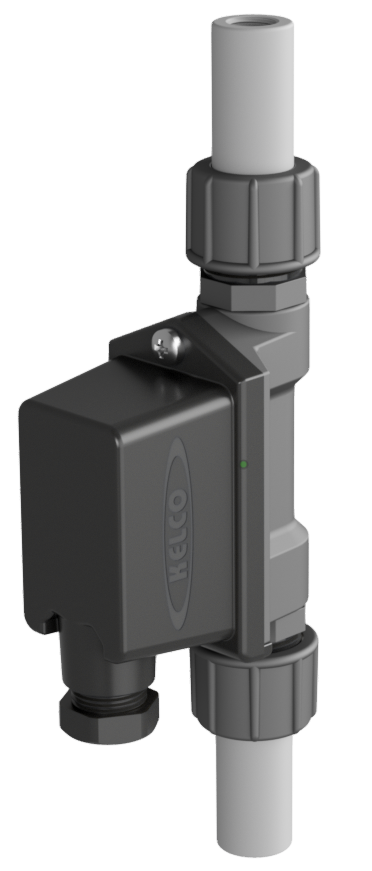
Super-sensitive version of the popular P20 inline flow switch — detects flows under 350 mL/hour. Pure-mechanical, magnetically-actuated, with no metal parts in contact with the liquid; ideal for monitoring chemical metering pumps, water treatment, cooling towers, and other low-flow industrial processes.
MF20 Series
Inline Flow Switches
Features
- Detects flows less than 350 mL/hour
- Suits tube sizes 6 to 20 mm (1/4″ to 3/4″) diameter
- No metal parts in contact with the liquid
- Suits pulsed or continuous flows
- 18 bar (260 psi) pressure rating
- Stable electrical response
- Very high flow-through capability
- Very low head loss
- Vertical mounting only
- Easy to install
- IP67 weatherproof electrical housing
- Liquid pH range 1 to 14
The MF20 body houses a fluted piston. Any flow (pulsed or continuous) lifts the piston up within the switch body until the liquid passes over it and out of the top. The piston contains a magnet that actuates an external reed switch through the polypropylene body — a simple gravity-return system that is exceptionally reliable and corrosion-proof. Three pistons are supplied with each MF20 (designated A, B, C) covering switch points from 0.32 L/h to 12.8 L/h. The MF20 is made from glass-reinforced polypropylene with Viton O-ring seals and PVC spigots — the only materials in contact with the liquid. It is supplied with tube flare fittings for 3 popular tube sizes (6 by 4, 8 by 4 and 12 by 9 flexible tube) and a set of ¾” unions and pipe spigots for direct fitting into 15 NB PVC or ABS pipework.
Select Model
Trade customers should contact sales@kelco.co.nz for account pricing.
Ordering — Available Models
| Model Number | Description |
|---|---|
| MF20-B | Dry reed switch S.P.S.T. N.O. — 50 W/VA, 250 V AC / 200 V DC, 1.5 A max. Not suitable for inductive loads. PLC and general control circuits. |
| MF20-C | Dry reed switch S.P.D.T. break before make — 20 W/VA, 140 V AC / 150 V DC, 1 A max. Not suitable for inductive loads. PLC and general control circuits. Less sensitive than B/R — the flow needed to switch on and off is twice the piston values (multiply the switching flow rates by 2.0). |
| MF20-R | Solid state relay (triac) S.P.S.T. N.O. — 740 W, 12 to 240 V AC, 4 A continuous (spike to 15 A); inductive loads 4 A at 240 V AC. AC control circuits and AC motor control. |
Operating Limitations
| Maximum recommended operating pressure (static or dynamic, ambient) | 1800 kPa / 260 psi |
|---|---|
| Minimum burst pressure (ambient) | 9700 kPa / 1400 psi |
| Maximum liquid temperature | 80 °C at 1 bar absolute (de-rate pressure linearly with temperature — see note) |
| Minimum liquid temperature | -30 °C |
| Maximum recommended continuous flow (water) | 25 L/min (head loss across the switch < 100 kPa at 25 L/min) |
| Liquid pH range | 1 to 14 |
| Ingress protection rating | IP67 |
| Flow sensitivity — piston A (default) | 0.32 L/h rising / 0.30 L/h falling (±10%); response time 4 s |
| Flow sensitivity — piston B (supplied) | 3.10 L/h rising / 3.05 L/h falling (±10%); response time 3 s |
| Flow sensitivity — piston C (supplied) | 12.8 L/h rising / 12.6 L/h falling (±10%); response time 2 s |
| Flow sensitivity — MF20-C | Less sensitive: for any given piston, multiply the switching flow rates above by 2.0. The A, B and C values above are for the MF20-B and MF20-R. |
| Flow sensitivity test basis | Water at 15 °C, accurate to ±10%. Changes in liquid viscosity or temperature affect the switching point: higher viscosity lowers the flow needed to actuate the switch and lengthens the response time; lower viscosity does the opposite. |
Dimensions
Warning: Electrical Safety
The MF20 Series flow switch is a mains voltage device. Death or serious injury may result if this switch is not correctly installed and operated. All electrical work on this switch must be performed by a fully qualified and licensed electrician.
Vertical Mounting Required
The MF20 must be mounted vertically with flow upward through the body. Gravity returns the piston to the off position when flow stops. There is a direction of flow arrow on the switch body — the switch will not operate against a reversed flow. The switch can be mounted directly on the suction or discharge valve of a metering pump.
Three Switch Points (Pistons A/B/C)
Three pistons ship with every MF20, each with an accurate and predictable switch point. The ‘A’ piston is fitted as standard (most sensitive); the ‘B’ and ‘C’ pistons are packed in the box. Switch points span 0.32 L/h to 12.8 L/h (MF20-B and MF20-R; the MF20-C needs twice the flow). The piston is changed by unscrewing the inlet adaptor (part No. 2) and inserting the new piston. The spanner octagon on the inlet adaptor accepts a standard gas cylinder spanner (28 mm across the flats).
Pulsed-Flow Behaviour
In pulsed-flow applications without a pulse dampener, if the pulse frequency is less than the electrical response time the MF20 may respond with a train of on/off pulses rather than a continuous on signal. Add a small in-line dampener if a steady output is needed.
Chemical Compatibility — DO NOT USE WITH
The MF20 wetted parts are glass-reinforced polypropylene with Viton O-ring seals (and PVC spigots). NEVER use this switch with: (1) sodium hypochlorite > 10% concentration; (2) ferrous or ferric solutions (e.g. ferric chloride); (3) solvents, hydrocarbons or alcohol solutions of any kind; (4) sulphuric acid > 50% concentration; (5) nitric acid > 20% concentration. For other media, use our Chemical Compatibility tool, widely available chemical compatibility charts for polypropylene and Viton, or ask Kelco.
Pressure De-rating at Elevated Temperatures
The 1800 kPa max operating pressure applies at 15 °C. Maximum operating pressure must be de-rated linearly in direct proportion to temperature increase, to a maximum of 1 bar absolute at 80 °C. In other words, only use this switch at elevated temperatures in non-pressurised systems that are totally open to atmosphere in all circumstances and under all conditions.
Clean Fluid & Line Filtration
The MF20 contains a close fitting piston and should only be used where the process fluid is reasonably clean and free of entrained or suspended material. Fluids containing large particulate matter, ferrous materials or fibrous matter should not be used in this switch. If the degree of contamination of the process fluid can’t be guaranteed, fit suitable line filtration upstream of the MF20.
Pipe & Tube Connections
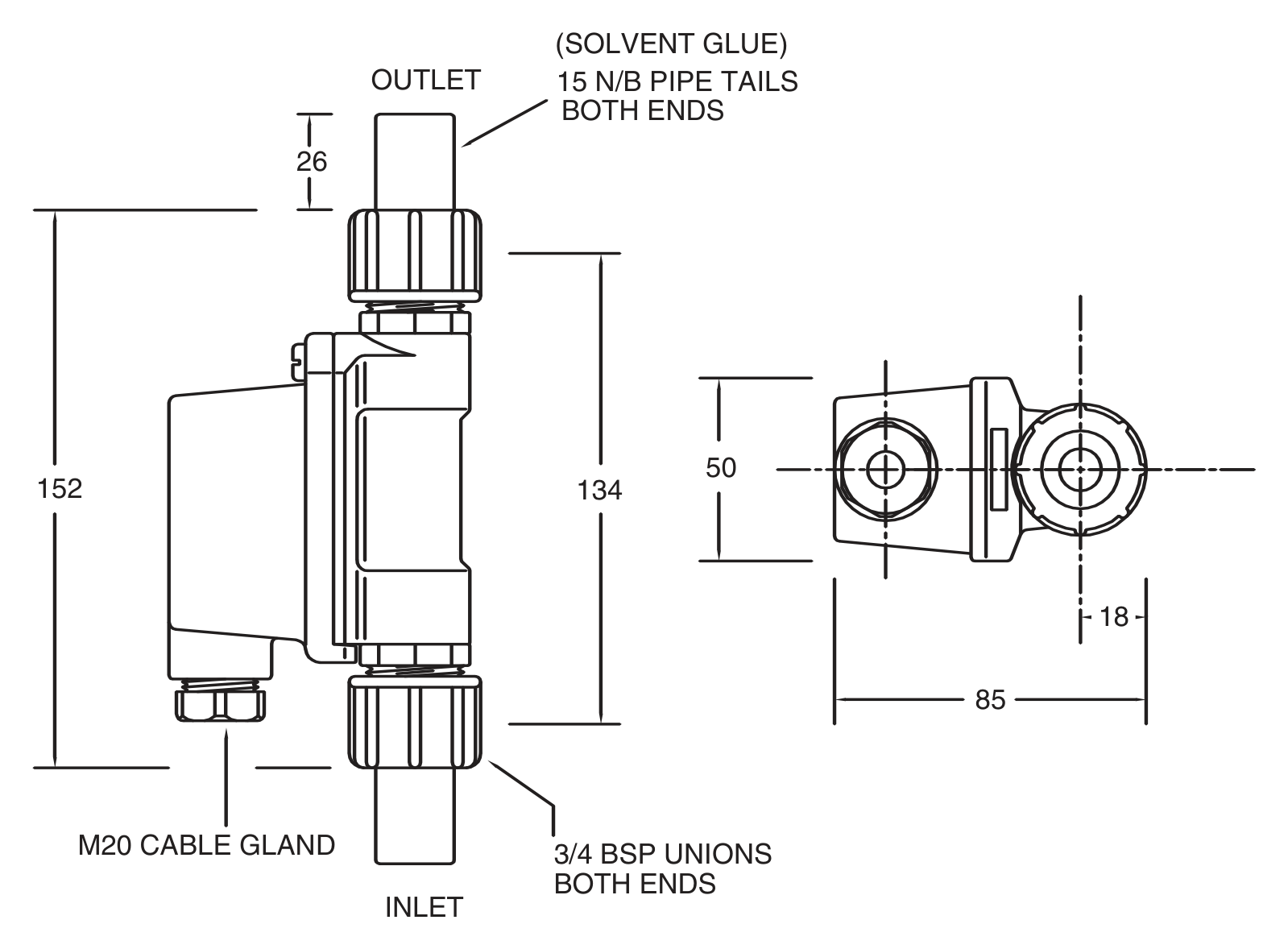
The MF20 is terminated with ¾” BSPP male threads, which can be screwed directly into pipe sockets and used in ¾” piping. It is also supplied with ¾” unions and ½” (15 NB) PVC spigots — thick walled, designed to be tapped ¼” BSP for compression fittings if required, and suitable for solvent gluing directly into 15 NB PVC or ABS pipe fittings — plus 3 sets of tube flare fittings to suit 6 by 4, 8 by 4 and 12 by 9 flexible tube.
Reed Switch Protection
The MF20 uses reed switches as the primary switching element. They offer an operating life in excess of 100 million cycles but must not be electrically overloaded. Where the reed switch is the main switch, use interposing relays and avoid inductive loads, and fit suitable protection such as diodes or rate effect suppression circuits. Avoid capacitive coupling effects on long cable runs by using shielded cable, and fit diode protection to the reed switches in DC applications.
Typical Applications
Control for backup dosing pumps, chemical metering pump control, chemical injection point status, laboratory applications, loss of prime detection and batch control.
Hazardous Areas
The MF20-B and MF20-C are simple apparatus under AS/NZS 60079.11 and may be used in a hazardous area only as part of an intrinsically safe circuit, connected through suitably certified associated apparatus. They are not Ex certified in their own right. The full conditions of use are given in the installation sheet. The MF20-R is not certified for use in hazardous areas and must not be installed in any area classified as hazardous under AS/NZS 60079.10 (Zone 0, 1, 2, 20, 21 or 22).
Serviceability
Fully field-serviceable. The electrical circuit boards are interchangeable; spare part kits are available for most components, and all of the components of the switch are available as spare parts, including the three pistons (A/B/C) and O-ring seals. Available from Kelco Engineering or your distributor.