
Reed Switch Application & Contact Protection
Comprehensive technical guide to reed switch characteristics, failure mechanisms, and the full range of practical protection methods for both DC and AC applications.
1. Introduction
Reed switches are elegant, highly reliable sensors and switching elements widely used in industrial control, security, telecommunications, HVAC, medical devices, and consumer electronics. Their sealed, contact-less construction makes them exceptionally resistant to contamination and vibration, and their inherently low contact resistance and galvanic isolation give them substantial advantages over solid-state alternatives in many signal-level applications.
However, reed switches operate within strict electrical limits. The glass-sealed ferromagnetic reed blades are extremely thin — typically 0.1 mm — and the contact gap is measured in microns. This precision construction is the source of their reliability, but also their greatest vulnerability. Electrical overloads — even brief transients lasting microseconds — can weld, pit, or fracture the contacts, destroying the switch instantly or degrading it progressively.
This guide provides a thorough treatment of reed switch characteristics, the physics of contact damage, and the complete range of practical protection methods for both DC and AC applications, covering every type of protection device in common use.
2. Construction & Operating Principles
2.1 Internal Construction
A reed switch consists of two ferromagnetic nickel-iron alloy blades (reeds) hermetically sealed inside a borosilicate glass tube, which is filled with an inert gas (typically nitrogen or a nitrogen/hydrogen blend) at above-atmospheric pressure. The reed tips are coated with a precious metal alloy — most commonly rhodium, ruthenium, or gold-over-nickel — to minimise contact resistance and prevent oxidation. The inert atmosphere and precious metal contacts together are the primary reasons for the switch’s exceptional contact stability over time.
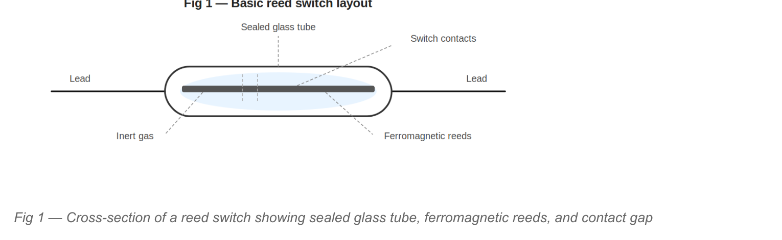
2.2 Operation
When a magnetic field of sufficient strength (the operate field, measured in ampere-turns or milli-Tesla) is applied axially or laterally to the switch, the two reeds adopt opposite magnetic polarity and are drawn together. The contact closure force is very small (typically 5–50 grams-force), the contact travel is extremely short (typically 50–100 µm), and the reed material is stressed well within its elastic limit during normal operation. When the magnetic field is reduced below the release field, the reeds’ own spring tension causes them to separate.
This purely mechanical operation — with no sliding action and no exposure of contact metal to atmosphere — is the basis of the reed switch’s long life, which can exceed 1 × 10⁹ operations when correctly applied.
2.3 Key Electrical Ratings
Every reed switch data sheet specifies a set of absolute maximum ratings that must never be exceeded simultaneously or individually. The four critical parameters are:
| Parameter | Typical Range | Significance |
|---|---|---|
| Switching voltage (Vmax) | 10 V to 500 V | Maximum voltage across open contacts — exceeding causes arc-over |
| Switching current (Imax) | 0.1 A to 3 A | Maximum current at the moment of contact make or break |
| Carry current (Icarry) | 0.5 A to 5 A | Maximum continuous current when contacts are closed (thermal limit) |
| Switching power (Wmax) | 10 W to 100 W | Governs contact erosion — most critical for AC resistive loads |
| Contact resistance | 50 mΩ to 200 mΩ | Increases with pitting/welding — monitor as degradation indicator |
CAUTION: All four power ratings must be satisfied simultaneously. A switch rated at 1 A / 200 V / 50 W cannot safely switch 1 A at 200 V (= 200 W). The most restrictive parameter governs.
3. Contact Failure Mechanisms
3.1 Inductive Kick (Back-EMF)
Any inductive load — relay coil, solenoid, motor winding, transformer primary — stores energy in its magnetic field proportional to ½LI². When the reed switch opens and interrupts current through this inductance, the collapsing magnetic field generates a back-EMF given by:
Vspike = L × (dI/dt)
Because the reed’s contact separation happens in microseconds, dI/dt is extremely large, producing voltage spikes that can reach tens or hundreds of times the supply voltage. This spike appears directly across the opening reed contacts, easily exceeding their breakdown voltage and causing a destructive arc. Repeated arcing erodes the precious metal contact coating, raises contact resistance, generates conductive metal vapour that bridges the gap, and ultimately welds or fractures the reeds.
3.2 Capacitive Inrush (Rate-of-Rise Effect)
When a reed switch closes into a capacitive load — including any circuit with significant cable capacitance or filter capacitors — the capacitor initially appears as a short circuit. The instantaneous current is limited only by the series resistance of the circuit, which is often very small. This current spike can briefly exceed the switch’s maximum switching current rating by an order of magnitude, causing contact micro-welding.
Long cable runs are a hidden source of capacitive loading. A 100 m run of typical screened cable can present 10–20 nF of capacitance — sufficient to cause significant inrush current when switching even modest DC voltages.
3.3 Incandescent Lamp Inrush
Cold tungsten filaments have a resistance approximately 10–15 times lower than their operating (hot) resistance. A 60 W / 240 V lamp has a hot resistance of ~960 Ω but a cold resistance of ~60–90 Ω, producing an inrush current of 2.5–4 A for a 240 V supply — often exceeding the reed’s switching current rating. Furthermore, this inrush lasts for 50–100 ms until the filament reaches temperature. Even LED lamps with capacitive switching power supplies can produce severe inrush currents.
3.4 Induced Voltages from Adjacent Wiring
Mains-frequency electric fields and high-frequency transients (generated by motor drives, power supplies, relays, or lightning) can couple inductively or capacitively into unshielded signal cables running in proximity. At the moment of switching, these induced voltages can exceed the reed’s contact rating even when the nominal load is well within specification.
4. Contact Protection in DC Circuits
In DC circuits, the dominant protection need is suppression of the inductive back-EMF spike. Several device types are available, each with different characteristics, advantages, and limitations. The correct choice depends on the supply voltage, the speed requirements of the circuit (how quickly the coil must de-energise), and the cost sensitivity.
4.1 Flyback Diode (Freewheeling Diode)
The flyback diode is the simplest, lowest-cost, and most effective solution for DC inductive load protection when circuit response time is not critical. The diode is connected in reverse-parallel with the inductive load (anode to negative rail, cathode to positive rail). When the reed switch opens, the inductive kick forward-biases the diode, which provides a low-impedance recirculation path for the collapsing current. The spike voltage is clamped to approximately one diode forward voltage drop (0.7 V) above the supply rail.
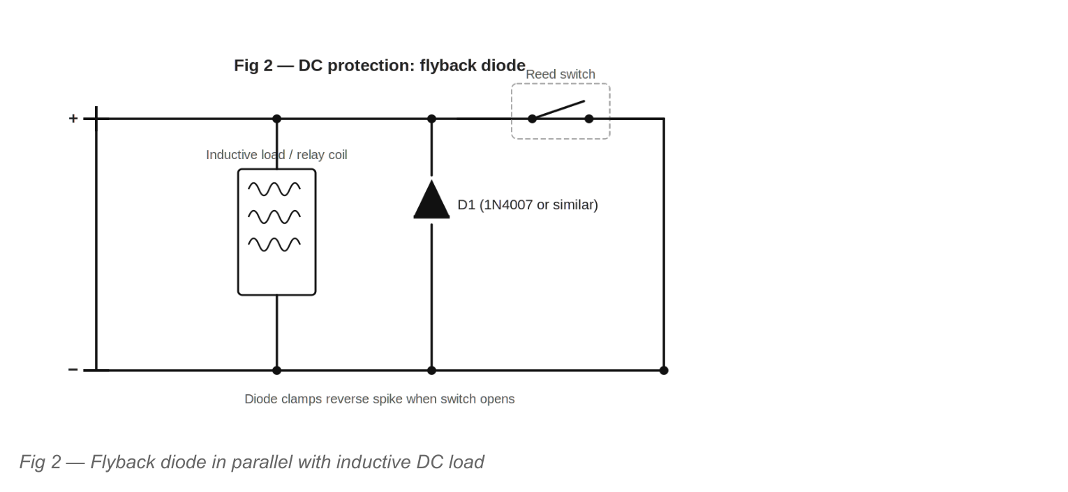
Component Selection
- Breakdown voltage — must exceed the supply voltage. For a 24 V DC system use a 50 V rated diode minimum; for a 48 V system use 100 V. A 2× safety margin is recommended.
- Current rating — must equal or exceed the coil’s steady-state current. Standard 1N4007 (1 A, 1000 V) suits most relay and solenoid coils to 24 V.
- Limitation — slow release: the diode extends coil de-energisation time significantly (by 5–10×) because the current decays slowly through the coil resistance. Use a Zener or TVS in series if fast release is required.
4.2 Zener Diode (Series with Flyback Diode)
Adding a Zener diode in series with the flyback diode (Zener anode to coil, flyback cathode to positive rail, with both in anti-series) clamps the back-EMF to a defined voltage (supply voltage + Zener voltage) rather than to one diode drop. This significantly increases the coil de-energisation speed — proportional to the clamping voltage — while still protecting the reed switch.
4.3 Transient Voltage Suppressor (TVS) Diode
The TVS (or Transzorb) diode is a purpose-designed clamping component with a very low dynamic impedance, capable of absorbing large energy transients in a very short time. Bidirectional TVS devices clamp both polarity spikes, making them suitable even when polarity reversal is possible. Unlike a standard Zener, the TVS is optimised for nanosecond-speed clamping of high-energy pulses.
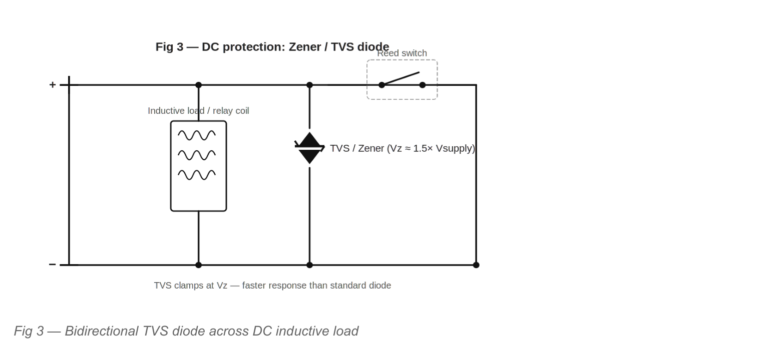
Component Selection
- Standoff voltage (Vr): select ≥ supply voltage. For 24 V DC use a 26 V or 28 V standoff TVS.
- Clamping voltage (Vc): must be below the reed’s maximum switching voltage. For a 26 V standoff TVS the clamping voltage at rated current is typically 42 V — well within a 200 V rated reed.
- Peak pulse power (Ppk): must exceed the energy stored in the inductance. Ppk = ½LI² / τ where τ is the damping time constant. 500 W to 1500 W devices (P6KE or 1.5KE series) suit most relay coil applications.
4.4 Metal Oxide Varistor (MOV)
The MOV (varistor) is a voltage-dependent resistor with a highly non-linear characteristic. Below its clamping voltage it presents a very high resistance; above it, resistance drops sharply and it absorbs the surge energy. MOVs are bidirectional and cost-effective, making them popular for both DC and AC applications.
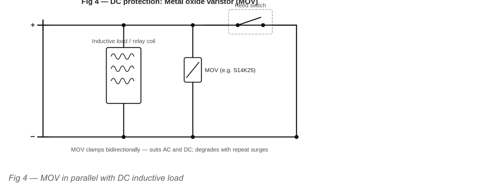
Component Selection
- Varistor voltage (Vnom): choose so that the device is in high-resistance state during normal operation. Vnom ≥ 1.2 × Vsupply for DC circuits. For 24 V DC use a 33 V or 39 V MOV.
- Energy rating (J): must exceed the coil stored energy. A 5 mH / 100 mA coil stores only 25 µJ — tiny compared to even a small MOV’s ratings.
- Degradation: MOVs degrade with each surge absorption. In high-cycle applications (>10,000 operations/day) consider replacing MOVs periodically or using TVS diodes which have lower degradation.
4.5 RC Snubber Network (Across the Reed Switch Contacts)
In addition to load-side clamping, an RC snubber connected directly across the reed switch contacts addresses the rate-of-rise problem. When the contacts open, the RC network provides an alternative current path, limiting the rate of voltage rise (dV/dt) across the contacts. This prevents the high dV/dt from re-igniting an arc across the opening contacts (a failure mode called ‘rate effect’ or ‘contact chatter’).
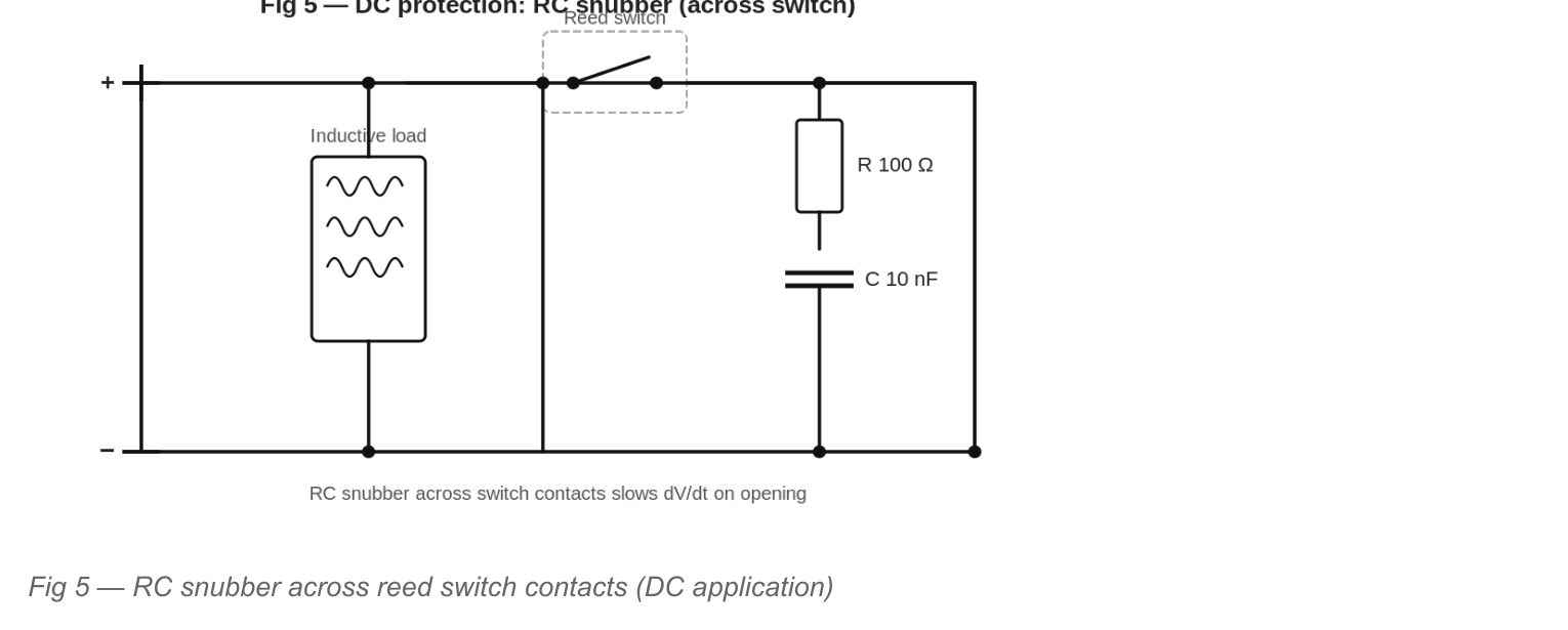
Component Selection — DC RC Snubber
For DC applications, the RC snubber is a secondary measure, supplementing a primary clamp (diode / TVS / MOV). Typical values:
- Resistor (R): 47 Ω to 470 Ω. The resistor limits capacitor inrush current back through the contacts on closure. Higher R = less inrush but less effective dV/dt limiting.
- Capacitor (C): 10 nF to 100 nF (non-polarised, X7R ceramic or film type). Must be rated for the supply voltage × 2. Film capacitors are preferred for pulse handling.
- Resistor power: P = ½CV²f where f = switching frequency. At 10 Hz, 24 V, 100 nF: P = 0.5 × 100 × 10⁻⁹ × 576 × 10 = 0.29 mW — negligible.
4.6 DC Best Practice — Combined Protection
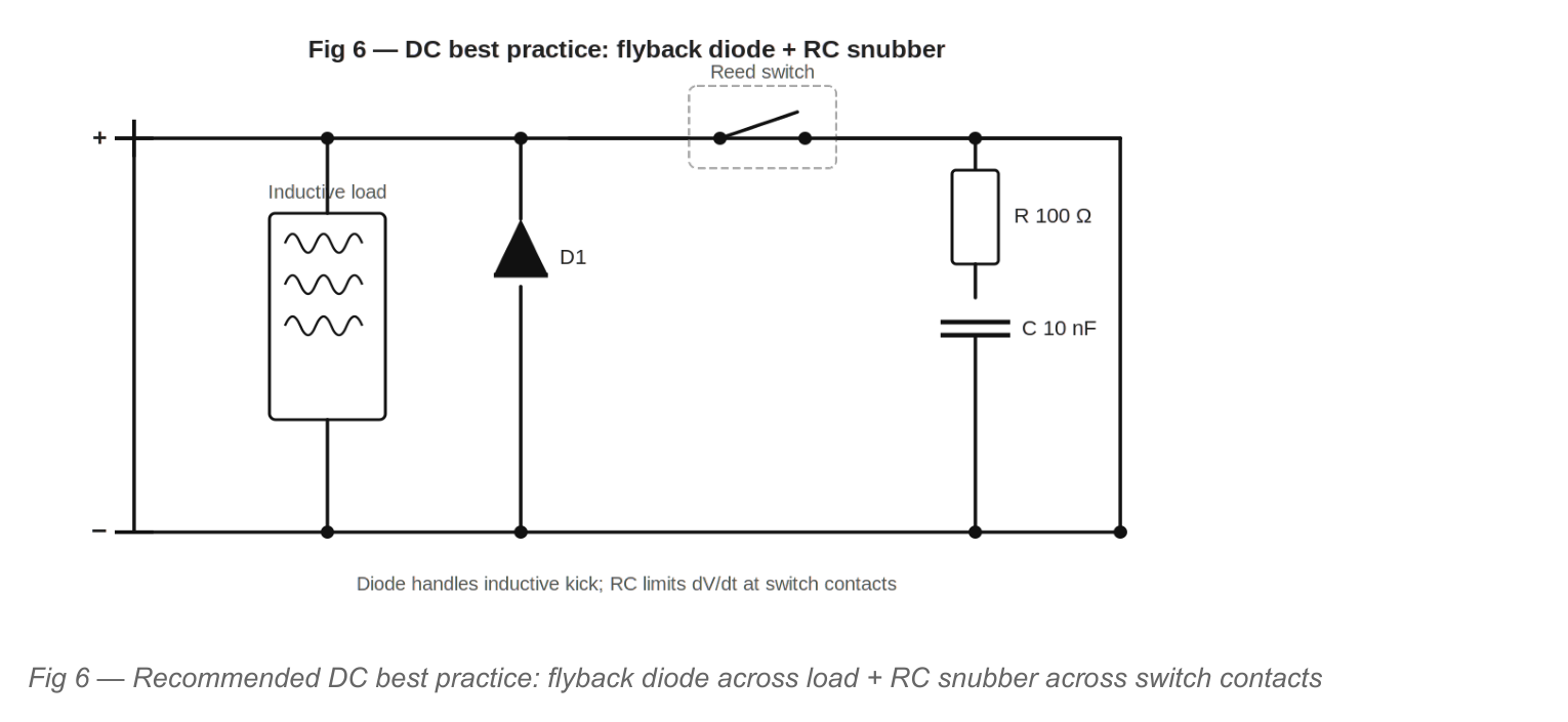
For robust DC inductive load switching, use both:
- Load-side: A flyback diode (or TVS for faster release) directly across the inductive load — this handles the energy absorption.
- Switch-side: An RC snubber (100 Ω + 10–47 nF) across the reed switch contacts — this limits dV/dt and suppresses contact bounce arcing.
4.7 DC Protection Device Comparison
| Device | Clamping Level | De-energise Speed | Bidirectional | Degrades | Best For |
|---|---|---|---|---|---|
| Flyback diode (1N4007) | Vsupply + 0.7 V | Slow (5–10×) | No | No | General DC relay/solenoid |
| Schottky diode | Vsupply + 0.3 V | Slow | No | No | Low-voltage (3.3 V, 5 V) logic |
| Zener + diode | Vsupply + Vz | Faster (2–5×) | No | Minor | Fast release needed |
| TVS diode | Vc per data sheet | Fast | Yes (bidir) | Low | High-energy or fast transients |
| MOV | ≈2× Vnom | Medium | Yes | Yes | AC/DC, cost-sensitive |
| RC snubber (across switch) | dV/dt limiting | N/A | Yes | No | Supplement to above |
5. Contact Protection in AC Circuits
AC applications present additional challenges. The alternating supply polarity means that unidirectional devices (standard diodes) cannot be used across the load. The AC waveform also repeatedly creates zero-crossings, making capacitive/inductive interactions more complex. The three principal protection methods for AC applications are RC snubbers, MOVs, and bidirectional TVS devices.
5.1 RC Snubber Network (Zobel Network) — Primary AC Protection
The series-RC network (sometimes called a Zobel network) connected across the inductive load is the standard and preferred AC protection method. It simultaneously addresses two hazards: the capacitor provides an alternative current path for the inductive kick energy when the switch opens, and the resistor limits the capacitor’s discharge current through the contacts when the switch re-closes.
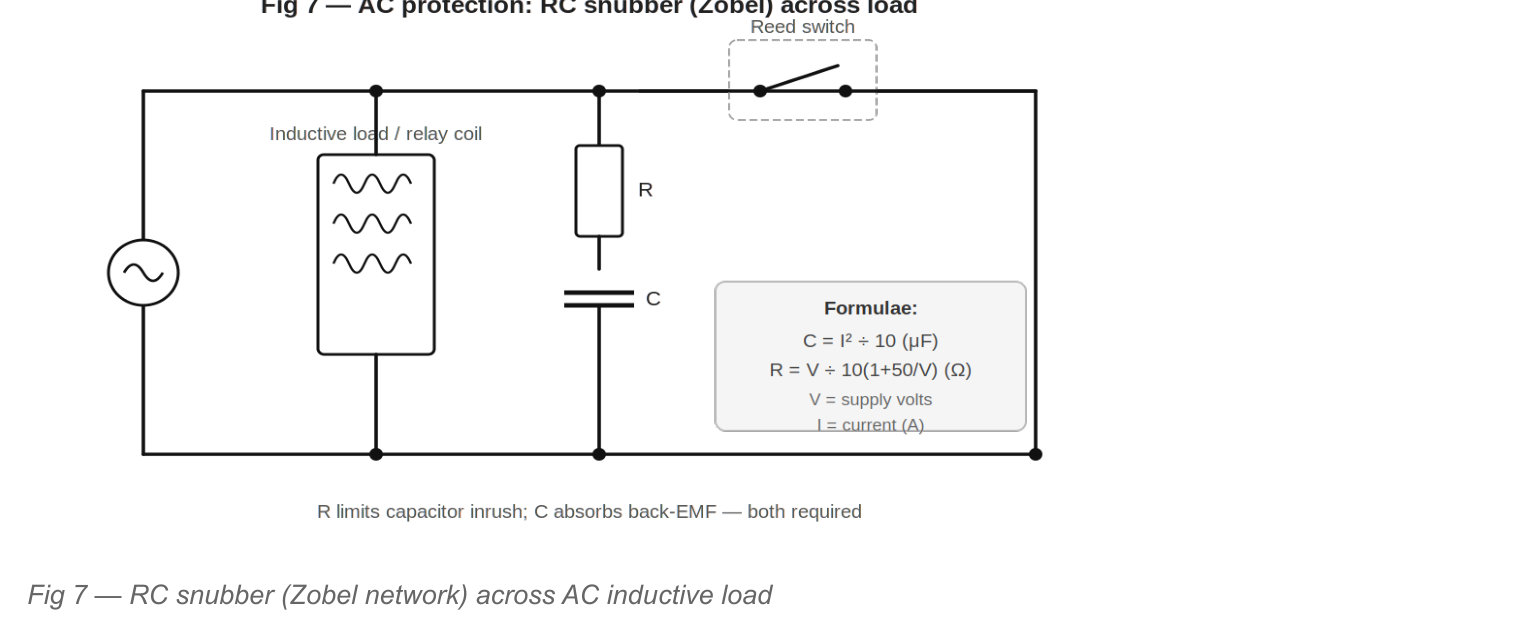
Component Selection — AC RC Snubber
The following formulae give practical starting values. Fine-tuning with an oscilloscope is recommended for final designs:
R (Ω) = V ÷ [10 × (1 + 50/V)]
| Supply (RMS) | Load Current | Recommended C | Recommended R | R Power Rating |
|---|---|---|---|---|
| 120 V AC | 0.1 A | 1 nF | 47 Ω | 1 W |
| 120 V AC | 0.5 A | 25 nF | 39 Ω | 3 W |
| 240 V AC | 0.1 A | 1 nF | 100 Ω | 2 W |
| 240 V AC | 0.5 A | 25 nF | 82 Ω | 5 W |
| 240 V AC | 1.0 A | 100 nF | 68 Ω | 10 W |
5.2 Metal Oxide Varistor (MOV) — AC Applications
MOVs are highly effective at absorbing high-energy voltage spikes on AC supplies, including those caused by inductive loads, power factor correction switching, and external transients. For AC, choose a device whose continuous AC voltage rating (Vac) equals or exceeds the supply RMS voltage, with an adequate safety margin.
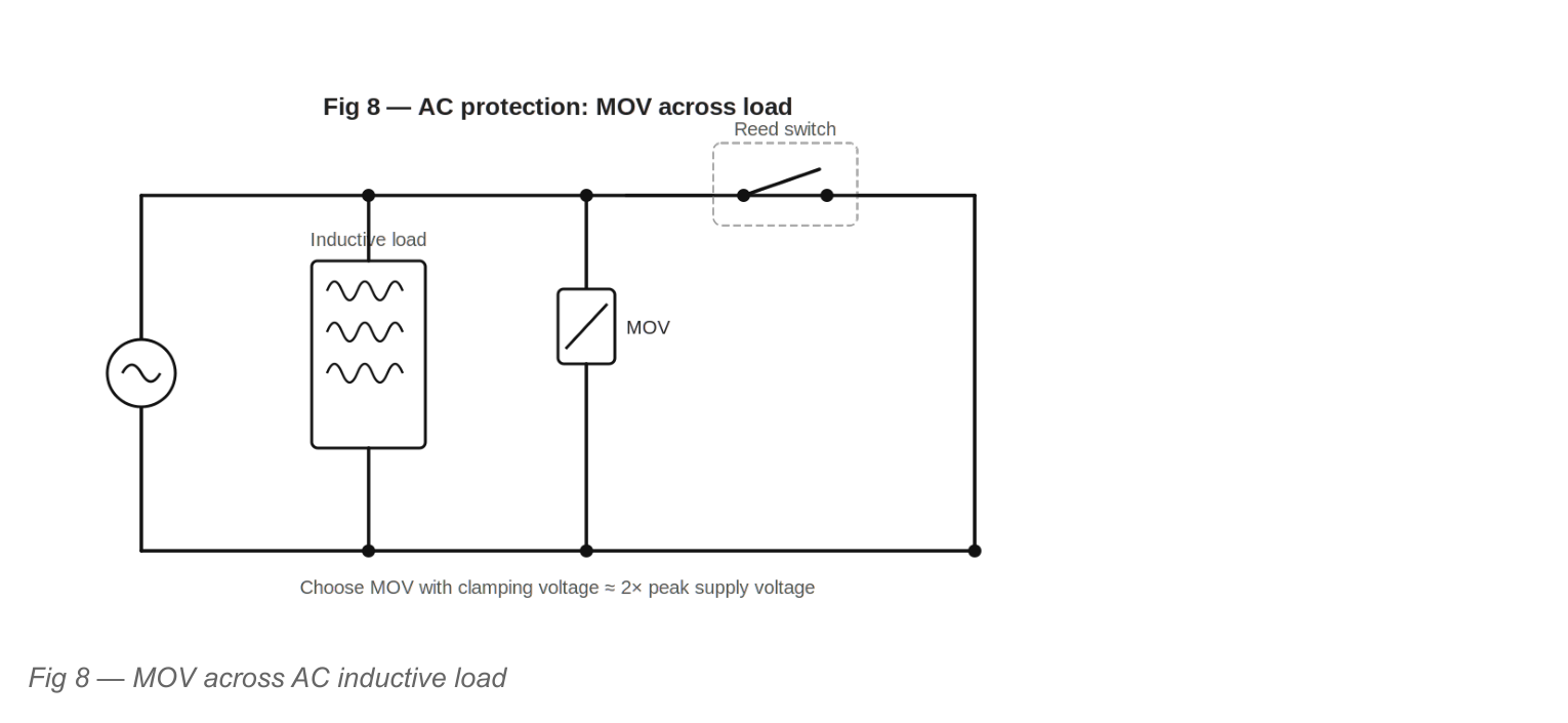
Component Selection — AC MOV
- AC voltage rating (Vac): minimum Vac ≥ Vsupply_RMS × 1.1 (10% overvoltage margin). For 240 V AC use a 275 V or 320 V MOV.
- Energy rating: must exceed ½LI². A 240 V / 0.5 A relay coil with L = 1 H stores 0.125 J — a 14 mm disc MOV (e.g. S14K275) can absorb up to 25 J.
- Limitation: the MOV alone does not fully limit dV/dt at the contacts on switching. For complete protection combine MOV with an RC snubber.
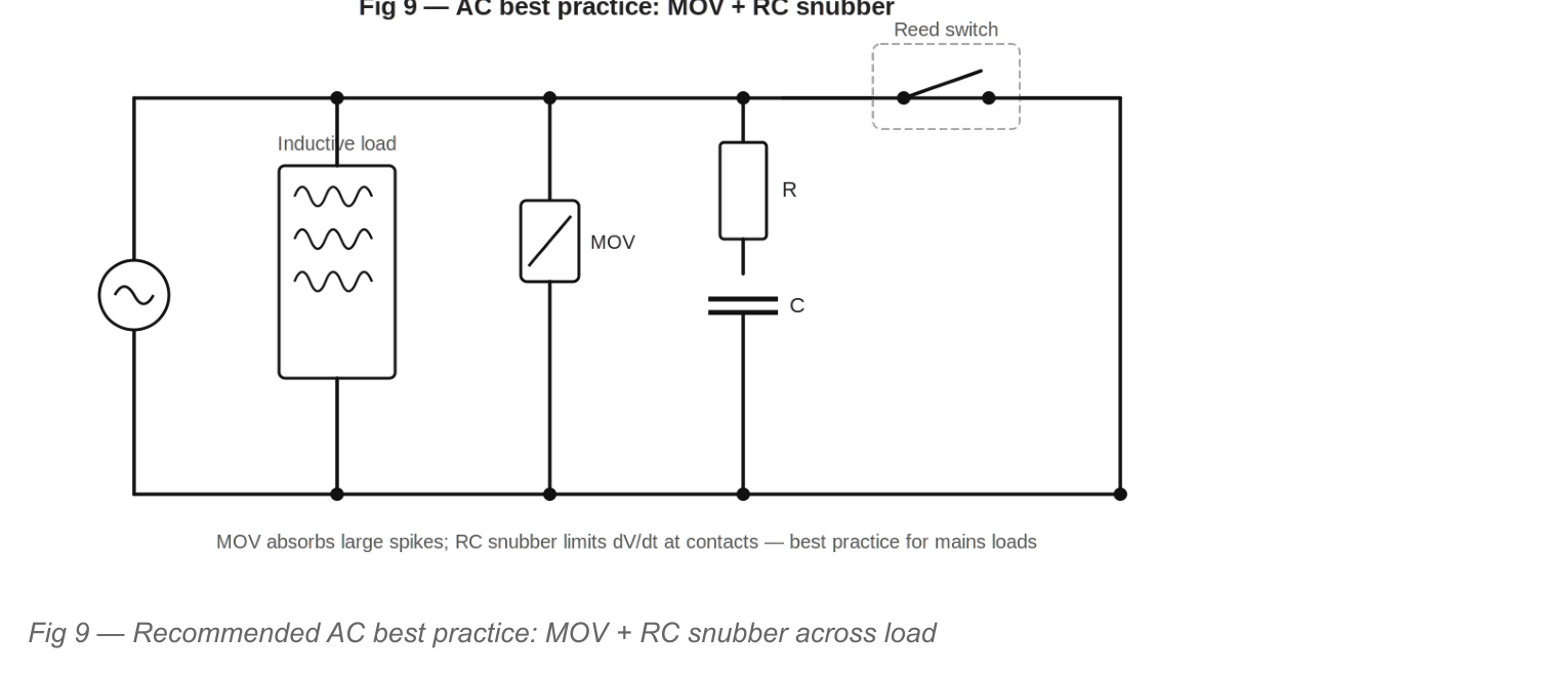
5.3 AC Best Practice — MOV Combined with RC Snubber
For the most demanding AC applications — large inductive loads, high-cycle operation, or sensitive reed switches — combine a MOV (to absorb large energy transients) with an RC snubber (to limit dV/dt and contact inrush). This two-device approach gives complementary protection at modest cost.
5.4 AC Protection Device Comparison
| Device | Clamps Spikes | Limits dV/dt | Energy Absorption | Polarity | Best For |
|---|---|---|---|---|---|
| RC snubber (Zobel) | Partially | Yes — primary function | Low (capacitor) | Bidirectional | All AC inductive loads — primary protection |
| MOV | Yes | Partially | High | Bidirectional | High-energy spikes, mains transients |
| Bidirectional TVS | Yes — precise | No | Medium | Bidirectional | Precise clamping level required |
| RC + MOV combined | Yes | Yes | High | Bidirectional | Best practice for demanding loads |
6. Special Load Considerations
6.1 Incandescent Lamp Loads
Incandescent and halogen lamps present a uniquely severe switching condition because of their extreme cold-to-hot resistance ratio. Direct switching with a reed switch will quickly destroy it unless current inrush is controlled. Three practical approaches exist:
- NTC thermistor in series: Connect a negative temperature coefficient (NTC) thermistor in series with the lamp. The NTC limits cold inrush without affecting steady-state current. Choose an NTC rated for the lamp current with a resistance of 5–20 Ω at 25 °C.
- Interposing relay: Use the reed switch to drive an interposing relay (see Section 7) or solid state relay (see Section 8) with the lamp connected to the relay’s power contacts.
- Series inductor: Add a series inductor (1–10 mH, rated for the lamp current) to limit the rate of current rise on contact closure. This is effective but large in physical size.
6.2 Electric Motor Loads
Reed switches must NOT be used to directly switch electric motor loads, including small DC motors. Even small motors (1–5 W) generate severe contact stresses from:
- High inrush current on starting (3–8× running current)
- Commutator arcing generating high-frequency voltage transients
- Back-EMF on stall or direction reversal
- Armature inductance producing switching spikes
For motor control applications, always use the reed switch as a signal input to a solid state motor driver, relay, or contactor rated for the motor load.
7. Interposing Relay
The interposing (intermediate) relay is the most universal protection technique. The reed switch drives only a small, low-power relay coil — which is well within its ratings and easily protected with a flyback diode — while the relay’s contacts, rated for the full load, handle the hazardous load. This provides complete electrical isolation between the sensitive reed switch circuit and the power circuit.
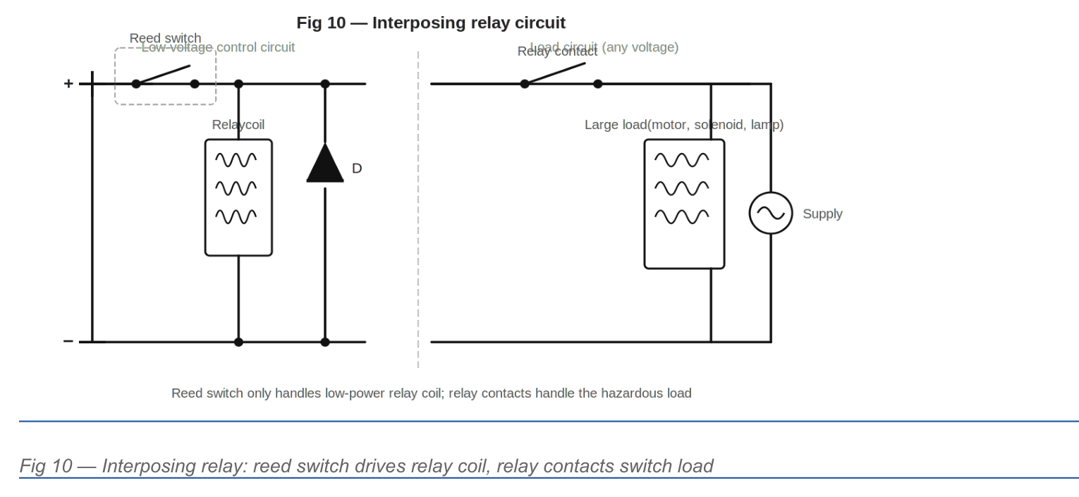
When to Use an Interposing Relay
- The load is inductive, capacitive, or a lamp — and adequate protection is complex or costly.
- The load voltage or current exceeds the reed switch’s maximum ratings.
- The load is a motor, contactor, or solenoid valve.
- Galvanic isolation between control circuit and load circuit is required.
- Long cable runs carry induced voltages from adjacent mains wiring.
8. Solid State Relay (SSR) Interface
Solid state relays are semiconductor devices that provide full electrical isolation between a low-power control input (typically 3–32 mA at 3–32 V DC) and a high-power load output (25 A, 280 V AC or higher). The control input is typically an LED driving an optical coupler, which draws only a few milliamps — well within reed switch ratings even without any protection components.
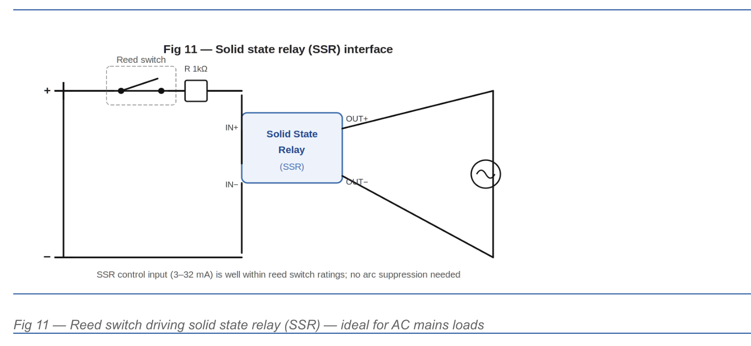
Advantages of the SSR Approach
- Zero-crossing switching (most AC SSRs switch only at AC zero-crossings) eliminates inrush current and arc generation entirely.
- No mechanical contacts in the load circuit — infinite load contact life.
- Control input is purely resistive — no inductive kick on the reed switch.
- Suits AC motor loads, large lamp arrays, and high-cycle applications.
9. Cable Selection & Installation Practices
9.1 Cable Type Selection
| Application | Cable Type | Reason |
|---|---|---|
| Reed switch signal, cable < 5 m, low-voltage DC | 2-core unshielded | Adequate for short, low-noise environments |
| Reed switch signal, cable 5–50 m | 2-core overall shielded (OS) | Shield drains induced EMI; connect shield at one end only |
| Reed switch in industrial environment | 2-core individually shielded | Rejects both common-mode and differential noise |
| Reed switch near VFD or motor cables | 2-core armoured + shielded (SWA + OS) | Armour provides mechanical protection; shield drains high-frequency noise |
| Reed switch adjacent to mains wiring in conduit | Separate conduit, minimum 100 mm separation | Physical separation is most effective EMI control method |
9.2 Shielding and Grounding Practice
- Single-end grounding: Connect cable shield to ground at ONE end only (typically the controller/PLC end) to prevent ground-loop currents.
- Shield continuity: The shield should be the outermost conductor and should completely enclose the signal conductors. Drain wire must make 360° contact with the connector shell at the grounded end.
- Separation: Do not route reed switch signal cables in the same conduit or cable tray as mains power wiring. Maintain minimum 100 mm separation (300 mm near VFDs).
- Loop area: At the reed switch itself, keep lead lengths as short as possible. Minimise the loop area formed by the switch and its connecting wires.
9.3 Cable Capacitance Effects
Long cable runs contribute capacitance in parallel with the reed switch contacts. When the switch opens, this capacitance charges through the load — creating an inrush current on the next contact closure. For cables over 20 m, measure or calculate cable capacitance (typically 100–200 pF/m for shielded cable) and ensure the RC snubber values account for this additional capacitance.
10. Protection Selection Guide
The following summary table provides a rapid selection guide based on load type and supply:
| Load Type | Supply | Minimum Protection | Recommended Best Practice |
|---|---|---|---|
| Resistive (pure) | DC or AC | None required* | RC snubber if cable > 10 m |
| Small signal relay coil | DC 5–48 V | Flyback diode across coil | Flyback diode + 100 Ω / 10 nF RC across switch |
| Large relay / solenoid | DC 12–48 V | Flyback diode or TVS across coil | TVS (1.5KE) across coil + RC across switch |
| Contactor coil | DC | TVS or MOV across coil | Interposing relay or SSR |
| Relay / solenoid coil | AC 110–240 V | RC snubber across coil | RC snubber + MOV across coil |
| Contactor / solenoid | AC 110–240 V | RC snubber + MOV | Interposing relay or SSR |
| Incandescent lamp | AC 110–240 V | NTC thermistor + RC snubber | Interposing relay or SSR |
| LED lamp (PSU type) | AC 110–240 V | RC snubber | Interposing relay or SSR |
| DC motor (any size) | DC | DO NOT switch directly | SSR + motor driver, or contactor |
| AC motor | AC | DO NOT switch directly | SSR or contactor via interposing relay |
NOTE: * Even resistive loads can cause transient problems on long cable runs (capacitive inrush) or in high-EMI environments. An RC snubber is always good practice.
11. Summary — Key Rules
- Ratings: Never exceed any of the four reed switch ratings: switching voltage, switching current, carry current, or switching power — all must be satisfied simultaneously.
- Inductive DC loads: All inductive loads in DC circuits must be fitted with a flyback diode, TVS, MOV, or RC snubber across the load coil — without exception.
- Inductive AC loads: All inductive loads in AC circuits must be fitted with a series-RC snubber across the load. Add a MOV for demanding applications.
- Switch-side RC: Add an RC snubber (100 Ω / 10–47 nF) directly across the reed switch contacts as supplementary protection for all inductive loads, and for any cable run over 10 m.
- Cabling: Use shielded cable for runs over 5 m, or in any environment with variable-speed drives, inverters, or mains-switching equipment nearby. Ground the shield at one end only.
- Interposing relay / SSR: Use an interposing relay or solid state relay for motor loads, large contactor coils, lamp loads, or any application where the load characteristics are uncertain or may change.
- Verification: Test each application with an oscilloscope across the reed switch contacts during normal operation. The voltage waveform at switch opening should not exceed 80% of the switch’s rated switching voltage.
12. Glossary
A unit used to measure the strength of a magnetic field. In the context of reed switches, it describes how strong a magnetic field needs to be to operate the switch, combining the electrical current and the number of wire coils producing the field.
A bright electrical spark that jumps across a gap — such as between opening switch contacts — when the voltage is high enough to ionise the surrounding air. Repeated arcing erodes contact surfaces and eventually destroys the switch.
The magnetic energy-storage property of a motor’s rotating winding. When current through a motor is interrupted, this stored energy produces a voltage spike that can damage switch contacts.
A voltage spike generated when the current through a coil, solenoid, or motor winding is suddenly cut off. As the magnetic field collapses, it drives a reverse voltage that can be many times the supply voltage and will damage unprotected switch contacts.
A heat-resistant, chemically stable glass used to form the sealed tube that houses a reed switch’s internal components, protecting the contacts from contamination and moisture.
The ability of a cable to store electrical charge between its conductors. Long cable runs can store enough charge to produce a damaging inrush current surge each time a switch closes.
The maximum continuous electrical current a closed reed switch can safely carry without overheating. This is a thermal limit separate from the switching current rating.
The maximum voltage a protection device (such as a TVS diode or MOV) will allow across a circuit before it begins conducting and absorbing the excess energy.
Electrical sparking that occurs inside a motor as current is transferred between the rotating armature coils and the stationary brushes. This generates high-frequency voltage disturbances that can damage nearby switch contacts.
Rapid, unintended opening and re-closing of switch contacts, often caused by electrical bounce or vibration. It accelerates contact wear and can cause circuit malfunctions.
The small electrical resistance present at the point where two switch contacts touch. A rising contact resistance over time is an indicator that contacts are being damaged by pitting or welding.
The rate at which electrical current changes over time. When a reed switch opens and interrupts current very rapidly, the large dI/dt through an inductance produces a high-voltage spike.
How quickly voltage increases across switch contacts as they open. An excessively fast voltage rise can re-ignite an electrical arc across the opening contacts — a failure mode known as the ‘rate effect.’
A bare wire running alongside a cable’s shielding layer, used to make a reliable electrical connection between the shield and the grounding point at one end of the cable.
Unwanted electrical noise radiated or conducted from nearby equipment — such as motors, variable frequency drives, or power supplies — that can interfere with sensitive signal circuits like reed switch wiring.
A diode connected in reverse across an inductive load that provides a safe, low-resistance path for current to circulate when the switch opens, preventing the inductive kick voltage from reaching the switch contacts.
The small voltage consumed by a diode when current flows through it in the normal (forward) direction — typically about 0.7 V for a standard diode, or about 0.3 V for a Schottky type.
Complete electrical separation between two circuits so that no direct current path exists between them. Prevents faults, high voltages, or noise in one circuit from affecting another.
An unwanted electrical current that flows in a loop formed when a cable shield is connected to ground at both ends and the two ground points are at slightly different voltages. Avoided by grounding the shield at one end only.
See Back-EMF. The voltage surge produced when current through a coil or motor winding is suddenly interrupted, caused by the collapsing magnetic field.
Any electrical device that stores energy in a magnetic field, such as a relay coil, solenoid, motor winding, or transformer primary. Inductive loads require protection components to prevent back-EMF damage to switch contacts.
A non-reactive gas — typically nitrogen or a nitrogen/hydrogen blend — used to fill the sealed glass tube of a reed switch, preventing the precious metal contacts from oxidising.
A brief, very large surge of current that flows when a switch first closes into a capacitive or cold-resistance load (such as a lamp or long cable), before the circuit reaches its normal steady state.
A small relay driven by the reed switch to operate a separate, larger set of contacts that handle the actual load. This keeps the reed switch well within its electrical ratings while allowing it to control heavy or hazardous loads.
A voltage-sensitive component that normally has very high resistance but rapidly conducts electricity and absorbs surge energy when voltage exceeds a set level. Suitable for use in both AC and DC circuits and provides bidirectional protection.
A unit of magnetic field strength used to specify the field required to operate or release a reed switch.
A resistor whose resistance decreases as it warms up (Negative Temperature Coefficient). Placed in series with a lamp load, it limits the high cold-start inrush current, then becomes nearly invisible to the circuit once it reaches operating temperature.
The minimum magnetic field strength required to pull a reed switch’s contacts together and close the circuit.
A component that transfers an electrical signal using a beam of light, providing complete electrical isolation between the input and output sides. Used in solid state relays to separate the low-power control circuit from the high-power load circuit.
The maximum instantaneous power a TVS diode can absorb during a brief transient event, measured in watts. The device must be selected so that this rating exceeds the energy stored in the protected inductance.
The thin coating of metals such as rhodium, ruthenium, or gold applied to the tip of each reed inside the switch. These coatings minimise contact resistance and prevent corrosion, contributing to the switch’s long service life.
A series combination of a resistor (R) and a capacitor (C) connected across a load or switch contacts. The capacitor absorbs voltage spikes; the resistor limits the capacitor’s discharge current back through the contacts when they re-close.
An electrically operated switch consisting of two thin, flexible ferromagnetic strips (reeds) hermetically sealed inside a glass tube. When a magnet is brought close, the reeds attract each other and make electrical contact; when the magnet is removed, they spring apart.
The magnetic field strength below which the spring tension of a reed switch’s contacts overcomes the magnetic attraction and the contacts separate, opening the circuit.
A type of semiconductor diode with a lower forward voltage drop (about 0.3 V) and faster switching speed than a standard diode. Preferred for protecting low-voltage circuits operating at 3.3 V or 5 V.
Electrical cable with a conductive outer layer wrapped around the signal wires to block interference from external electric and magnetic fields. Essential for reed switch wiring in electrically noisy environments.
The practice of connecting a cable’s shielding layer to ground at only one end (typically at the controller). This prevents ground-loop currents from flowing through the shield and generating noise.
A relay with no moving parts that uses semiconductor devices to switch electrical loads. It accepts a small control current from a reed switch and can switch large AC loads, typically turning on only when the AC voltage waveform crosses zero to eliminate inrush and arcing.
The maximum continuous voltage a TVS diode can withstand without beginning to conduct. Must be selected to be at least equal to the normal supply voltage of the circuit being protected.
The maximum electrical current the reed switch is permitted to make or break at the exact moment its contacts open or close. Exceeding this causes contact micro-welding.
The maximum electrical power (voltage multiplied by current) the reed switch can safely handle at the moment of switching. This rating governs long-term contact erosion and is often the most restrictive of the four key ratings.
The maximum voltage that may appear across the open reed switch contacts. Exceeding this level can cause electrical breakdown and an arc to jump across the contact gap.
A brief, sudden spike or surge in voltage or current, lasting from nanoseconds to a few milliseconds, that can damage sensitive components if uncontrolled. Common sources include switching inductive loads, lightning, and power-line disturbances.
A semiconductor device designed specifically to clamp voltage spikes very rapidly, protecting circuits from transient damage. Available in bidirectional versions suitable for AC circuits or circuits where voltage polarity may reverse.
An electronic motor controller that varies motor speed by changing the frequency of its power supply. VFDs generate significant high-frequency electrical noise that can interfere with nearby signal cables and reed switch circuits.
The rated voltage of a Metal Oxide Varistor at which it transitions from its normal high-resistance state to its conducting, energy-absorbing state. Selected to be safely above the normal circuit operating voltage.
A special diode that, when connected in reverse, conducts at a precise, predictable voltage known as its Zener voltage. Used in series with a flyback diode to clamp back-EMF to a defined level while allowing the coil to de-energise faster than a plain flyback diode alone would permit.
A feature of most AC solid state relays that delays the switching action until the AC supply voltage passes through zero volts. This eliminates inrush current surges and contact arcing that would otherwise occur if switching happened at a peak in the voltage waveform.
Another name for an RC snubber network when used in AC circuits. It consists of a resistor and capacitor connected in series across an inductive load. The capacitor provides a path for the inductive energy spike when the switch opens, while the resistor prevents the capacitor from discharging too quickly back through the contacts when the switch re-closes. The name comes from engineer Otto Zobel, who developed the underlying network theory.
DISCLAIMER
This document is provided by Kelco Engineering Pty Ltd (“Kelco”) for general estimation purposes only and does not constitute engineering advice. While every reasonable effort has been made to ensure the accuracy of the documents and data presented, Kelco makes no warranty, representation or guarantee, express or implied, as to the completeness, accuracy, reliability or suitability of the results for any particular purpose. The selection, application and installation of flow sensing equipment containing or using reed switches is solely the responsibility of the user.
Kelco accepts no liability whatsoever — whether in contract, tort (including negligence), statute or otherwise — for any loss, damage, injury or expense arising directly or indirectly from the use of, or reliance upon, the information provided in this document. Users should independently verify all results and consult qualified engineering professionals before making design or procurement decisions.
Use of this document constitutes acceptance of these terms.
© 2026 Kelco Engineering Pty Ltd. Contact Sales@Kelco.com.nz for engineering enquiries.